15EDG KF2EDG PCB Screw Terminal Blocks
Official Store Deal
Expert Analysis Overview
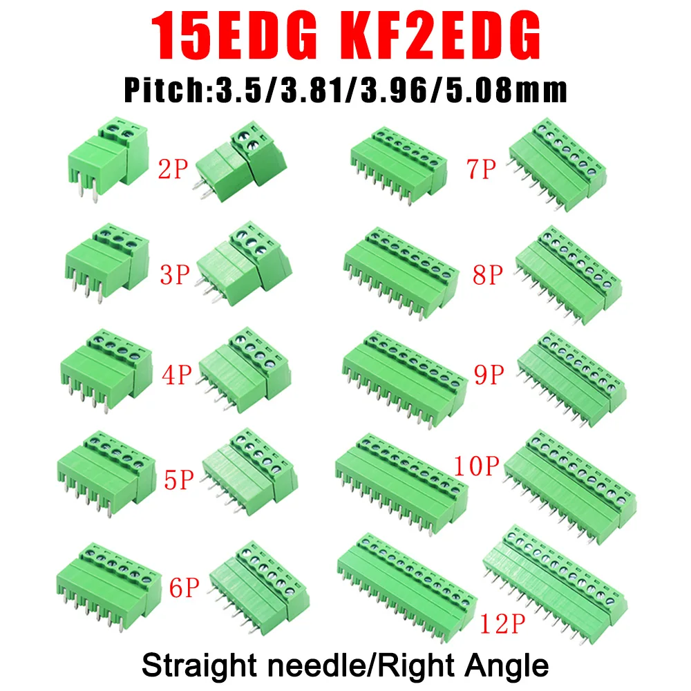
Precision in Connectivity: Understanding Pitch and Pin Configurations
The 15EDG KF2EDG PCB Screw Terminal Blocks are essential modular connectors designed for reliable wire termination in diverse electronic circuits. These components are critical for establishing secure, removable electrical connections on printed circuit boards. The product offers a comprehensive range of pitch sizes, including 3.5mm, 3.81mm, 3.96mm, and 5.08mm, catering to various design requirements and industry standards. Each pitch size dictates the spacing between adjacent pins, directly influencing the current carrying capacity and the physical footprint on a PCB.Different pitch options allow for precise integration into existing or new circuit layouts. For instance, the smaller 3.5mm and 3.81mm pitches are often utilized in compact electronic devices where space is at a premium, such as consumer electronics or embedded systems. Larger pitches like 3.96mm and 5.08mm provide greater clearance between terminals, which can be advantageous for higher voltage applications or when using thicker gauge wires, reducing the risk of arcing or short circuits. This variety ensures compatibility across a broad spectrum of electrical engineering projects. The selection of the correct pitch is paramount for circuit integrity.
Unlike generic, fixed-pitch terminal blocks, this offering provides a versatile selection. This adaptability means engineers do not need to compromise on layout or wire gauge. The availability of 2-pin to 14-pin configurations, in both male plug and female socket formats, further enhances their utility. This modularity allows for custom solutions, from simple two-wire connections to complex multi-channel interfaces. The choice between straight needle and right-angle orientations also provides flexibility in board design, accommodating different enclosure constraints and wire routing paths. Right-angle connectors are particularly useful for applications requiring a low-profile connection or where wires need to exit parallel to the PCB surface. This broad selection is a significant advantage.
Ensuring Secure Connections: The Mechanics of Screw Terminals
The fundamental design of these terminal blocks centers on the screw-down mechanism, which provides a robust and reliable method for securing wires. Each terminal features a metal clamp actuated by a screw, which firmly presses against the stripped end of a wire. This mechanical compression creates a low-resistance electrical contact, crucial for preventing power loss and heat generation. The integrity of this connection directly impacts system performance.Proper wire termination with screw terminals minimizes the risk of intermittent connections, a common failure point in many electrical systems. The screws are typically made from plated steel, offering good conductivity and corrosion resistance. The plastic housing, visible in the product images, appears to be a standard polyamide or similar engineering plastic, providing adequate insulation and mechanical stability. This material choice is critical for safety. The design ensures that once a wire is tightened, it remains securely in place, even under moderate vibration or mechanical stress. This stability is vital for long-term reliability in industrial or automotive applications where movement is common.
Compared to solder connections, screw terminals offer the distinct advantage of easy field serviceability. Wires can be quickly connected or disconnected without specialized tools or soldering expertise. This simplifies maintenance and troubleshooting. Unlike crimp connectors, which require specific crimping tools and dies for each wire gauge, screw terminals are more forgiving and adaptable to a range of wire sizes within their specified limits. This flexibility reduces tool investment. The ability to visually inspect the wire termination before tightening the screw also adds a layer of confidence in the connection's quality, a feature not always present with other connection methods. This ease of use is a significant operational benefit.
Material Integrity and Electrical Safety: A Critical Examination
The visible green plastic housing of these terminal blocks suggests a standard, robust polymer, likely a flame-retardant material such as PA66. Such materials are chosen for their electrical insulation properties and mechanical strength, which are essential for preventing short circuits and providing structural support for the conductors. The color green is a common identifier for terminal blocks, often indicating a general-purpose application. The housing must withstand operational temperatures.While specific insulation ratings (e.g., UL, CE) are not explicitly stated in the product title or images, the design implies adherence to common electrical safety practices. The enclosed nature of the wire entry points and the separation between terminals are fundamental safety features. The metal components, including the screws and internal contacts, are typically brass or phosphor bronze, often nickel or tin-plated to enhance conductivity and resist oxidation. These materials ensure efficient current flow. The quality of these metallic contacts directly influences the terminal block's ability to handle specified current loads without excessive heating, which is a primary concern for electrical fire prevention. Verifying the wire gauge accuracy for the intended application is non-negotiable.
Unlike lower-grade connectors that might use inferior plastics prone to brittleness or poor heat resistance, these appear to utilize a standard, reliable compound. The implied current rating, based on the pitch sizes and screw terminal design, would typically range from 6A to 15A per terminal for these types of connectors, depending on the specific pitch and wire gauge used. For example, a 5.08mm pitch terminal block is generally rated for higher currents than a 3.5mm pitch. Always consult the manufacturer's datasheet for precise current and voltage ratings to ensure compliance with safety standards and prevent electrical fires. Overloading terminals is a serious hazard.
Versatility in Application: Integrating into Circuit Designs
These PCB screw terminal blocks are inherently versatile, finding utility across a broad spectrum of electronic and electrical applications. Their primary function is to provide a reliable interface between external wiring and a printed circuit board. This makes them indispensable in industrial control systems, where sensors, actuators, and power supplies need to be connected to control boards. The ability to quickly swap out components or reconfigure wiring without soldering is a major advantage in these environments. They are also widely used in home automation projects.In a scenario where a custom circuit board needs to interact with various external components, these terminal blocks simplify the wiring process significantly. For example, in a DIY project involving a microcontroller and several peripheral modules, these connectors allow for neat and organized wiring, reducing clutter and improving troubleshooting ease. The male plug and female socket design ensures a secure, yet detachable, connection. This modularity is a key benefit. This allows for pre-wiring harnesses that can be quickly plugged into the PCB, streamlining assembly and reducing potential wiring errors during installation. The straight and right-angle options further enhance their adaptability to different enclosure designs and space constraints.
Compared to direct soldering of wires to a PCB, which is permanent and difficult to modify, these terminal blocks offer superior flexibility. Unlike crimp-on connectors that might require specialized tools, these only need a small screwdriver for installation. This makes them a more accessible option for hobbyists and professionals alike. Their use extends to power supplies, LED lighting systems, security systems, and various prototyping boards. The robust connection they provide ensures stable operation in critical applications. This broad applicability makes them a staple in any electronics workshop or production line.
Longevity and Reliability: Investing in Stable Electrical Pathways
The long-term reliability of any electrical connection is paramount, and these PCB screw terminal blocks are designed to offer sustained performance. The robust mechanical connection provided by the screw mechanism resists loosening over time, a common issue with spring-loaded terminals under vibration. This stability is crucial for maintaining consistent electrical contact. The materials chosen for the housing and contacts contribute significantly to their durability.When properly installed, these terminal blocks can withstand numerous connection and disconnection cycles without significant degradation. The plastic housing is engineered to resist environmental factors such as moderate temperature fluctuations and humidity, which can otherwise compromise insulation integrity. The metal contacts, being plated, are protected against oxidation, ensuring low contact resistance throughout their operational life. This resistance to environmental wear is a key factor. This means fewer maintenance interventions and a longer operational lifespan for the connected equipment, translating into reduced downtime and operational costs. Investing in quality connectors prevents future headaches.
Unlike cheaper, flimsy alternatives that might use brittle plastics or unplated contacts, these components appear to meet standard expectations for durability. The visible construction suggests a product intended for reliable, long-term use in various applications, from consumer electronics to light industrial controls. The ability to maintain a secure connection over years of operation is a testament to their design. This reliability ensures that the electrical pathways remain stable, preventing signal loss or power interruptions that could lead to system failures. This makes them a cost-effective choice in the long run, as they reduce the need for frequent replacements or repairs. They offer peace of mind.
Installation Best Practices: Achieving Optimal Electrical Performance
Proper installation is critical for maximizing the performance and safety of these PCB screw terminal blocks. The process begins with accurate wire preparation. Wires must be stripped to the correct length, typically around 5-7mm, ensuring that no bare conductor extends beyond the terminal block's housing after insertion. This prevents accidental short circuits. The wire strands should be twisted tightly to prevent stray strands from causing issues. This attention to detail is essential.Once the wire is prepared, it is inserted into the terminal opening, and the screw is tightened. The tightening torque is important; it should be firm enough to secure the wire without over-tightening, which can damage the wire strands or strip the screw threads. A small, appropriately sized screwdriver is recommended for this task. Over-tightening can compromise the connection. A visual inspection after tightening confirms that the wire is fully seated and no bare copper is exposed. This step ensures both electrical integrity and safety. For multi-pin connectors, it is good practice to tighten all screws evenly to distribute pressure.
Compared to quick-connect terminals, which rely on spring pressure, screw terminals offer a more tactile feedback during installation, allowing the installer to feel the wire being secured. Unlike solder connections, which require heat and flux, these are a cold connection method, simplifying installation in sensitive environments. Always verify the wire gauge is compatible with the terminal block's capacity. Using an undersized wire can lead to overheating, while an oversized wire may not fit securely. Adhering to these best practices ensures a safe and reliable electrical connection. This attention to detail prevents costly failures.
The Value Proposition: Beyond the Initial Cost
The true value of these 15EDG KF2EDG PCB screw terminal blocks extends far beyond their initial purchase price. Their robust design and versatile configurations contribute significantly to the overall reliability and longevity of any electronic system they are integrated into. Investing in quality connectors reduces the likelihood of costly failures and rework. This translates into substantial savings over the product's lifecycle.By providing secure and stable electrical connections, these terminal blocks help prevent intermittent faults, which are notoriously difficult and time-consuming to diagnose. The ease of maintenance and modification they offer, compared to permanent soldering, further enhances their economic value. This reduces labor costs for repairs. For prototyping, their reusability and flexibility accelerate development cycles, allowing engineers to iterate designs more quickly and efficiently. This speed to market is invaluable.
Unlike cheaper, less reliable alternatives that might require frequent replacement or lead to system instability, these terminal blocks offer a dependable solution. Their broad compatibility with various wire gauges and PCB layouts means fewer different parts to stock, simplifying inventory management. This consolidation saves money. The peace of mind that comes from knowing critical connections are secure and compliant with safety standards is an intangible but significant benefit. This product represents a smart investment in system integrity and operational efficiency, ensuring that your electrical projects remain stable and serviceable for years to come. Imagine your projects running flawlessly, free from connection worries, with the flexibility to adapt and maintain with ease.