CKCTINNER Dupont Jumper Wire Kit (10-40cm, 10/20/40pin)
Official Store Deal
Expert Analysis Overview
The CKCTINNER Dupont Jumper Wire Kit is an essential, versatile connectivity solution designed for electronics enthusiasts, educators, and solar energy hobbyists building and testing low-power circuits. This kit provides the fundamental links needed for rapid prototyping and system integration.
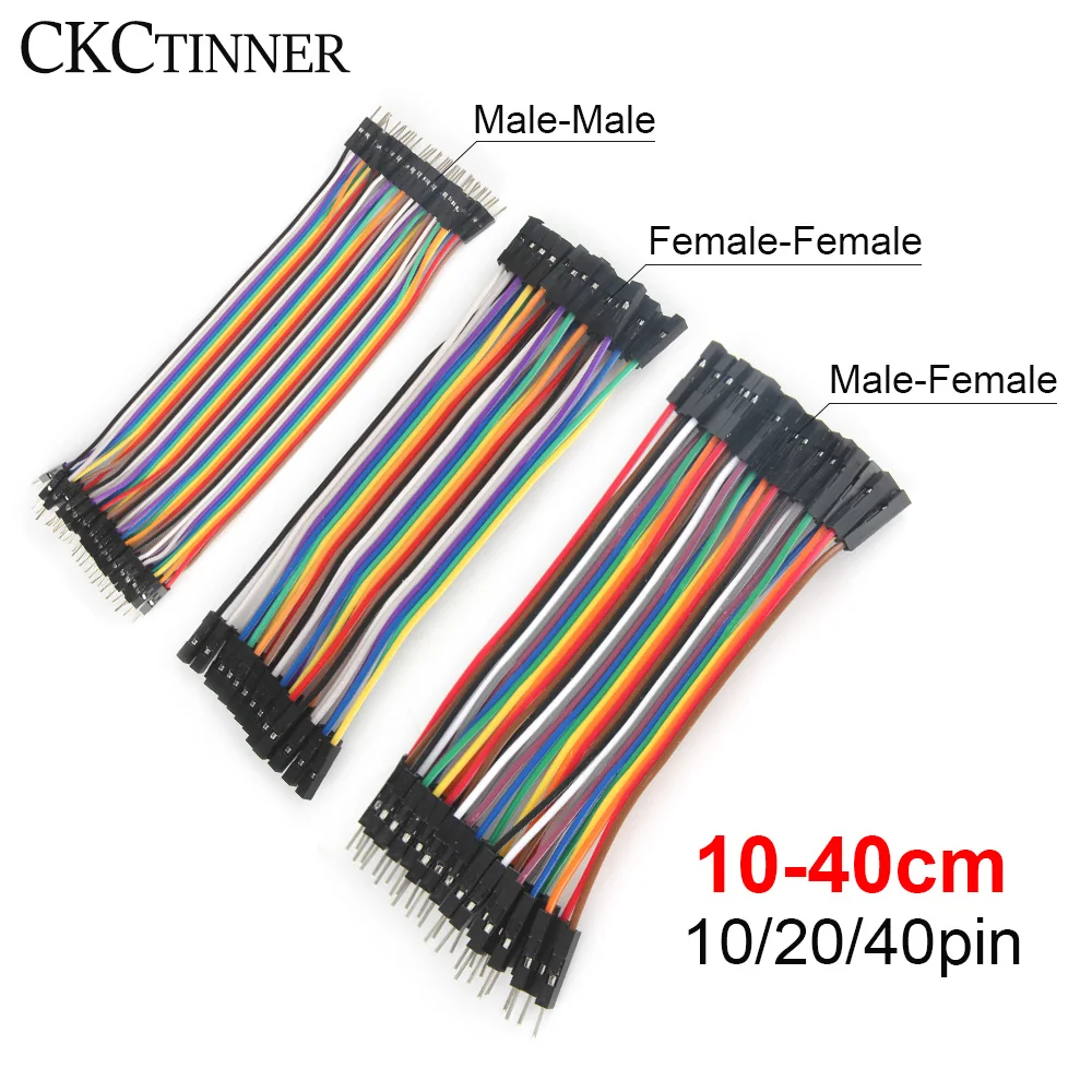
The CKCTINNER Dupont Jumper Wire Kit visually presents itself as a highly organized and comprehensive collection of connectivity solutions. It features distinct bundles, clearly labeled as Male-Male, Female-Female, and Male-Female configurations. Each bundle contains multiple individual wires, with options for 10, 20, or 40 pins, catering to various project complexities. The wires themselves are vibrantly color-coded in a standard rainbow spectrum, a crucial visual aid for circuit identification. Lengths are available from 10cm to 40cm. This range of options is substantial.
For the solar energy hobbyist, this variety translates directly into unparalleled flexibility for prototyping and testing. Imagine setting up a small-scale solar charging circuit on a breadboard. The Male-Male wires connect your microcontroller to the breadboard rails, while Female-Female wires link a solar charge controller module to a battery monitor. Male-Female wires then bridge the gap between the male pins of a sensor and the female headers of your development board. This adaptability streamlines the initial setup phase. Complex layouts become manageable.
Unlike basic starter kits that often provide only one type or length of jumper wire, this comprehensive assortment eliminates the need for inconvenient workarounds or additional purchases. Generic wires might lack consistent color coding, leading to frustrating debugging sessions. The CKCTINNER kit, conversely, acts as a foundational upgrade, providing all necessary connection types from the outset. This significantly reduces project setup time. It saves valuable effort.
The wires appear to be standard 22-26 AWG (American Wire Gauge) stranded copper, insulated with PVC. The close-up images clearly show gold-plated pins or sockets, encased within black plastic shrouds. This combination of materials suggests a focus on both conductivity and basic insulation for prototyping environments. The stranded copper offers inherent flexibility.
For low-voltage DC applications common in solar projects, such as connecting a small solar panel to an Arduino or ESP32, these wires facilitate stable power and data transmission. The stranded copper construction provides resilience against repeated bending, which is invaluable during iterative design and testing phases. This reduces the risk of internal wire breakage. Consistent signal integrity is maintained. When integrating components like an MPPT controller with a battery management system (BMS) for a small LiPo battery bank, these wires ensure that control signals and low-current power lines remain stable. The gold plating on the connectors helps resist oxidation, maintaining a low-resistance contact over time, crucial for accurate sensor readings and efficient power delivery in a self-sustaining energy system.
Compared to solid core wires, which are prone to fatigue and breakage from frequent manipulation, stranded wires offer superior durability in a prototyping context. While not designed for the high-current demands of a primary solar panel array, they are perfectly suited for the control and monitoring circuits that govern such systems. This distinction is important. The kit provides an upgrade over flimsy, uninsulated wires often found in rudimentary kits, offering a more professional and reliable connection. It supports iterative design.
The distinct rainbow color coding across all wire types (male-male, female-female, male-female) is immediately apparent and consistent. This spectrum, often following a standard resistor color code sequence or a simple ROYGBIV pattern, is a widely recognized convention in electronics. The bundles are neatly organized, suggesting attention to user experience. This visual clarity is paramount.
This visual organization significantly reduces the time spent tracing wires and debugging circuits, a common frustration in complex setups. For a solar energy hobbyist integrating multiple sensors—like temperature, humidity, or light intensity sensors—into a single microcontroller, quickly identifying power, ground, and specific signal lines becomes instantaneous. This direct visual cue minimizes human error during assembly and troubleshooting. Debugging becomes faster. The mental load of managing numerous connections is considerably lightened, allowing more focus on the logic and functionality of the solar project rather than the physical wiring itself.
Without such clear color distinctions, troubleshooting can become a tedious process of trial and error, particularly when dealing with numerous sensor inputs and actuator outputs in a sophisticated solar monitoring system. Monochromatic wires, or those with inconsistent color schemes, necessitate constant continuity checks or laborious tracing, consuming valuable project time. The consistent rainbow coding of the CKCTINNER kit, conversely, acts as an immediate visual map, making it a significant upgrade over less organized alternatives. It is a time-saver.
The range of lengths, from 10cm to 40cm, provides substantial flexibility for various breadboard layouts and component placements. The availability of 10, 20, and 40-pin bundles allows for tailoring the wire count precisely to specific project needs, whether it is a simple sensor connection or a complex multi-channel data acquisition system. This adaptability is key for diverse projects.
Whether prototyping a small solar charger for a portable device, designing a more elaborate off-grid lighting controller, or even building a remote weather station powered by a miniature solar panel, the appropriate wire length and quantity are readily available. This prevents the clutter of excessively long wires, which can introduce noise and make circuits difficult to manage, or the frustration of too-short connections that strain components. Optimal wire management is crucial for clean, reliable circuits. For complex off-grid systems, space optimization is often a concern, and having the right length wire contributes to a compact and efficient design. It supports diverse project scales.
Relying on a single length or type of jumper wire often leads to either messy, tangled circuits that are prone to accidental disconnections or the need for inconvenient extensions and splicing. This comprehensive kit, unlike basic starter packs, ensures that the right connection is always at hand, supporting diverse project scales and physical layouts. It allows for a more professional and organized approach to prototyping. The kit supports scalability.
The thin gauge of these wires, while appropriate for signal and low-current applications, indicates a specific resistance per unit length. The visible PVC insulation appears standard for indoor use, providing adequate protection against incidental contact. The connectors are simple friction-fit types, designed for ease of insertion and removal. Wire resistance is a factor.
For sensitive measurement circuits, particularly when calculating efficiency losses in a solar setup, understanding the inherent resistance of these wires is important. While negligible for digital signals, even small voltage drops across longer wires can impact analog readings from sensors or slightly reduce the power delivered to low-power components like LEDs or small motors. For instance, a 0.1V drop can significantly affect the accuracy of a battery voltage sensor. Power integrity is critical. Users designing precise solar energy monitoring systems must account for these minor resistive losses, especially when wires are extended or multiple connections are made in series. This ensures accurate data.
Unlike heavy-gauge power cables designed for minimal voltage drop over long distances in a main solar array, these jumper wires are optimized for flexibility and ease of use in a prototyping environment. This represents a strategic trade-off: maximum flexibility and convenience versus minimal resistance. Users must factor in slight resistive losses when precise voltage or current measurements are required, or when powering components sensitive to voltage fluctuations. This is a design consideration. The transparency here informs users about the product's optimal use case.
The connectors are standard 2.54mm pitch, which is the universal spacing for breadboards, Arduino headers, Raspberry Pi GPIOs, and many other development boards. The male pins are square, ensuring a secure fit into breadboard holes and female headers, while the female sockets are designed for a snug, reliable connection with male pins. This ensures broad compatibility within the electronics ecosystem.
This universal pitch ensures that the wires integrate seamlessly into almost any existing solar experimentation setup involving microcontrollers or sensor arrays. Whether connecting a light-dependent resistor (LDR) to an analog input pin on an Arduino for solar tracking or linking a current sensor to a Raspberry Pi for power consumption monitoring, these wires provide the necessary bridge. Verifying compatibility with existing solar setups becomes a non-issue for the prototyping phase, allowing hobbyists to focus on the functional aspects of their projects. Integration is straightforward. The ability to connect diverse components without compatibility hurdles accelerates the development of complex, self-sustaining energy systems.
Proprietary connectors or non-standard pitches can severely limit the utility of prototyping components, forcing users into specific ecosystems and restricting hardware choices. These Dupont wires, conversely, act as a universal translator, enabling diverse hardware to communicate and interact without custom adapters. They are a universal standard. This open compatibility is a significant advantage over less flexible wiring solutions, empowering users to mix and match components from various manufacturers with confidence. It offers true freedom.
Imagine the satisfaction of rapidly assembling a new solar charging circuit, confidently connecting sensors, and watching your custom energy monitor come to life without a single soldering iron touch. Envision the streamlined debugging process, where every connection is clear, color-coded, and perfectly matched to your components. This kit empowers rapid innovation, turning complex ideas into working prototypes with unprecedented speed and reliability. Your next solar project will progress with efficiency and precision, allowing more time for creative design and less for frustrating troubleshooting.
The Backbone of Circuit Prototyping
The CKCTINNER Dupont Jumper Wire Kit visually presents itself as a highly organized and comprehensive collection of connectivity solutions. It features distinct bundles, clearly labeled as Male-Male, Female-Female, and Male-Female configurations. Each bundle contains multiple individual wires, with options for 10, 20, or 40 pins, catering to various project complexities. The wires themselves are vibrantly color-coded in a standard rainbow spectrum, a crucial visual aid for circuit identification. Lengths are available from 10cm to 40cm. This range of options is substantial.
For the solar energy hobbyist, this variety translates directly into unparalleled flexibility for prototyping and testing. Imagine setting up a small-scale solar charging circuit on a breadboard. The Male-Male wires connect your microcontroller to the breadboard rails, while Female-Female wires link a solar charge controller module to a battery monitor. Male-Female wires then bridge the gap between the male pins of a sensor and the female headers of your development board. This adaptability streamlines the initial setup phase. Complex layouts become manageable.
Unlike basic starter kits that often provide only one type or length of jumper wire, this comprehensive assortment eliminates the need for inconvenient workarounds or additional purchases. Generic wires might lack consistent color coding, leading to frustrating debugging sessions. The CKCTINNER kit, conversely, acts as a foundational upgrade, providing all necessary connection types from the outset. This significantly reduces project setup time. It saves valuable effort.
Ensuring Reliable Energy Flow for Small-Scale Systems
The wires appear to be standard 22-26 AWG (American Wire Gauge) stranded copper, insulated with PVC. The close-up images clearly show gold-plated pins or sockets, encased within black plastic shrouds. This combination of materials suggests a focus on both conductivity and basic insulation for prototyping environments. The stranded copper offers inherent flexibility.
For low-voltage DC applications common in solar projects, such as connecting a small solar panel to an Arduino or ESP32, these wires facilitate stable power and data transmission. The stranded copper construction provides resilience against repeated bending, which is invaluable during iterative design and testing phases. This reduces the risk of internal wire breakage. Consistent signal integrity is maintained. When integrating components like an MPPT controller with a battery management system (BMS) for a small LiPo battery bank, these wires ensure that control signals and low-current power lines remain stable. The gold plating on the connectors helps resist oxidation, maintaining a low-resistance contact over time, crucial for accurate sensor readings and efficient power delivery in a self-sustaining energy system.
Compared to solid core wires, which are prone to fatigue and breakage from frequent manipulation, stranded wires offer superior durability in a prototyping context. While not designed for the high-current demands of a primary solar panel array, they are perfectly suited for the control and monitoring circuits that govern such systems. This distinction is important. The kit provides an upgrade over flimsy, uninsulated wires often found in rudimentary kits, offering a more professional and reliable connection. It supports iterative design.
The Efficiency of Connection Management
The distinct rainbow color coding across all wire types (male-male, female-female, male-female) is immediately apparent and consistent. This spectrum, often following a standard resistor color code sequence or a simple ROYGBIV pattern, is a widely recognized convention in electronics. The bundles are neatly organized, suggesting attention to user experience. This visual clarity is paramount.
This visual organization significantly reduces the time spent tracing wires and debugging circuits, a common frustration in complex setups. For a solar energy hobbyist integrating multiple sensors—like temperature, humidity, or light intensity sensors—into a single microcontroller, quickly identifying power, ground, and specific signal lines becomes instantaneous. This direct visual cue minimizes human error during assembly and troubleshooting. Debugging becomes faster. The mental load of managing numerous connections is considerably lightened, allowing more focus on the logic and functionality of the solar project rather than the physical wiring itself.
Without such clear color distinctions, troubleshooting can become a tedious process of trial and error, particularly when dealing with numerous sensor inputs and actuator outputs in a sophisticated solar monitoring system. Monochromatic wires, or those with inconsistent color schemes, necessitate constant continuity checks or laborious tracing, consuming valuable project time. The consistent rainbow coding of the CKCTINNER kit, conversely, acts as an immediate visual map, making it a significant upgrade over less organized alternatives. It is a time-saver.
Versatility in Off-Grid Prototyping
The range of lengths, from 10cm to 40cm, provides substantial flexibility for various breadboard layouts and component placements. The availability of 10, 20, and 40-pin bundles allows for tailoring the wire count precisely to specific project needs, whether it is a simple sensor connection or a complex multi-channel data acquisition system. This adaptability is key for diverse projects.
Whether prototyping a small solar charger for a portable device, designing a more elaborate off-grid lighting controller, or even building a remote weather station powered by a miniature solar panel, the appropriate wire length and quantity are readily available. This prevents the clutter of excessively long wires, which can introduce noise and make circuits difficult to manage, or the frustration of too-short connections that strain components. Optimal wire management is crucial for clean, reliable circuits. For complex off-grid systems, space optimization is often a concern, and having the right length wire contributes to a compact and efficient design. It supports diverse project scales.
Relying on a single length or type of jumper wire often leads to either messy, tangled circuits that are prone to accidental disconnections or the need for inconvenient extensions and splicing. This comprehensive kit, unlike basic starter packs, ensures that the right connection is always at hand, supporting diverse project scales and physical layouts. It allows for a more professional and organized approach to prototyping. The kit supports scalability.
Calculating and Mitigating Minor Losses
The thin gauge of these wires, while appropriate for signal and low-current applications, indicates a specific resistance per unit length. The visible PVC insulation appears standard for indoor use, providing adequate protection against incidental contact. The connectors are simple friction-fit types, designed for ease of insertion and removal. Wire resistance is a factor.
For sensitive measurement circuits, particularly when calculating efficiency losses in a solar setup, understanding the inherent resistance of these wires is important. While negligible for digital signals, even small voltage drops across longer wires can impact analog readings from sensors or slightly reduce the power delivered to low-power components like LEDs or small motors. For instance, a 0.1V drop can significantly affect the accuracy of a battery voltage sensor. Power integrity is critical. Users designing precise solar energy monitoring systems must account for these minor resistive losses, especially when wires are extended or multiple connections are made in series. This ensures accurate data.
Unlike heavy-gauge power cables designed for minimal voltage drop over long distances in a main solar array, these jumper wires are optimized for flexibility and ease of use in a prototyping environment. This represents a strategic trade-off: maximum flexibility and convenience versus minimal resistance. Users must factor in slight resistive losses when precise voltage or current measurements are required, or when powering components sensitive to voltage fluctuations. This is a design consideration. The transparency here informs users about the product's optimal use case.
Compatibility and System Integration
The connectors are standard 2.54mm pitch, which is the universal spacing for breadboards, Arduino headers, Raspberry Pi GPIOs, and many other development boards. The male pins are square, ensuring a secure fit into breadboard holes and female headers, while the female sockets are designed for a snug, reliable connection with male pins. This ensures broad compatibility within the electronics ecosystem.
This universal pitch ensures that the wires integrate seamlessly into almost any existing solar experimentation setup involving microcontrollers or sensor arrays. Whether connecting a light-dependent resistor (LDR) to an analog input pin on an Arduino for solar tracking or linking a current sensor to a Raspberry Pi for power consumption monitoring, these wires provide the necessary bridge. Verifying compatibility with existing solar setups becomes a non-issue for the prototyping phase, allowing hobbyists to focus on the functional aspects of their projects. Integration is straightforward. The ability to connect diverse components without compatibility hurdles accelerates the development of complex, self-sustaining energy systems.
Proprietary connectors or non-standard pitches can severely limit the utility of prototyping components, forcing users into specific ecosystems and restricting hardware choices. These Dupont wires, conversely, act as a universal translator, enabling diverse hardware to communicate and interact without custom adapters. They are a universal standard. This open compatibility is a significant advantage over less flexible wiring solutions, empowering users to mix and match components from various manufacturers with confidence. It offers true freedom.
Imagine the satisfaction of rapidly assembling a new solar charging circuit, confidently connecting sensors, and watching your custom energy monitor come to life without a single soldering iron touch. Envision the streamlined debugging process, where every connection is clear, color-coded, and perfectly matched to your components. This kit empowers rapid innovation, turning complex ideas into working prototypes with unprecedented speed and reliability. Your next solar project will progress with efficiency and precision, allowing more time for creative design and less for frustrating troubleshooting.