Dual-Relay Automatic Power Switching Module
Official Store Deal
Expert Analysis Overview
Uninterrupted Power Management: A Technical Overview
The Dual-Relay Automatic Power Switching Module is a critical component designed for seamless power transition and battery charging management, targeting systems requiring continuous operation despite fluctuating primary power sources. This device addresses the fundamental vulnerability of critical loads to power interruptions, offering an engineered solution for automatic failover to a backup battery supply. Its compact form factor belies a robust functionality, making it an indispensable asset for embedded systems, emergency lighting, and small-scale uninterruptible power supply (UPS) applications where reliability is paramount. The module's design prioritizes both efficient power switching and intelligent battery maintenance, ensuring longevity for connected energy storage.
The Architecture of Redundancy: Seamless Power Transition
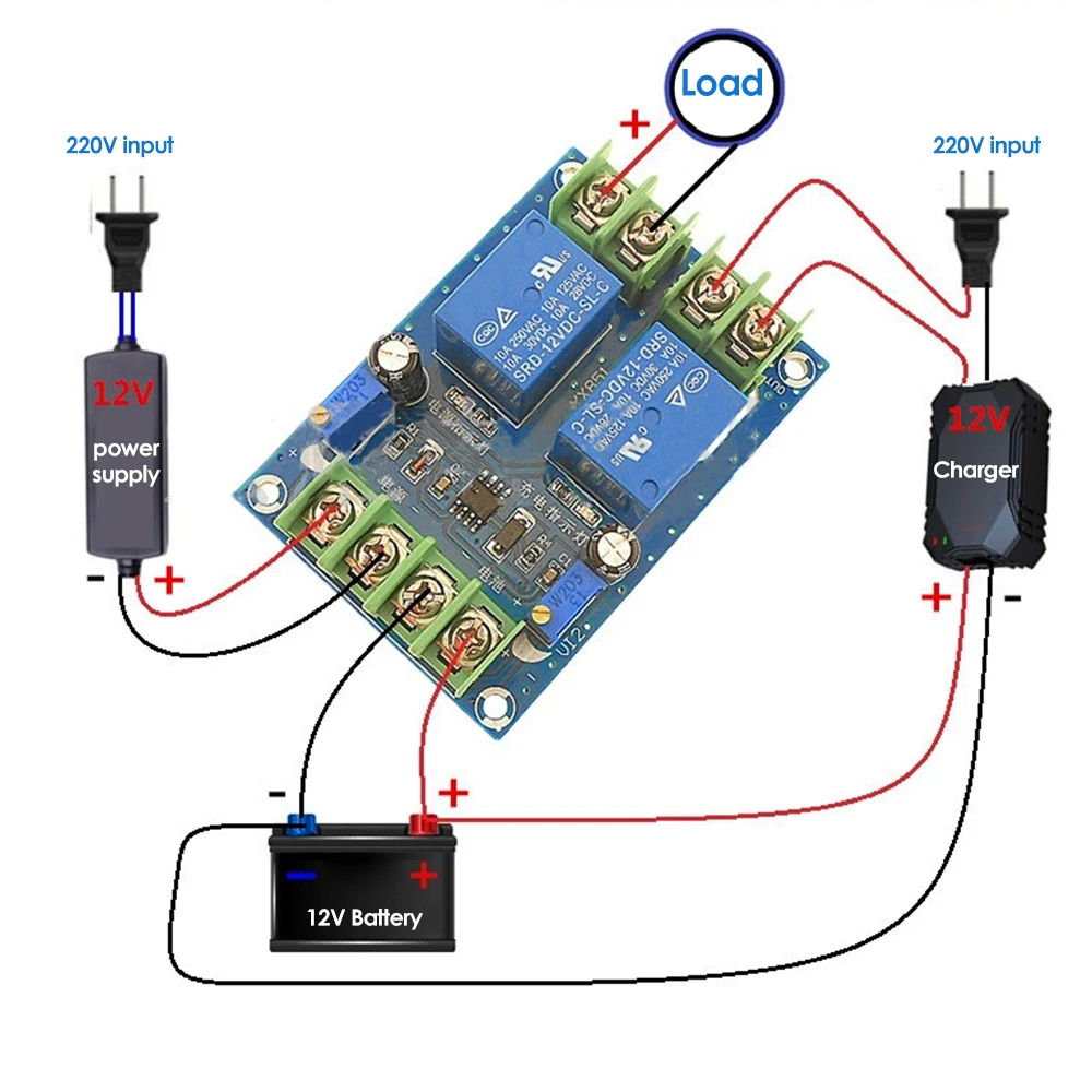
The core functionality of this module revolves around its ability to automatically switch between a primary AC power supply (via a charger) and a 12V DC battery. This is not merely a simple switch; it is an intelligent failover mechanism. When the primary 220V input is active, the module prioritizes power delivery to the load directly from the rectified and regulated source, simultaneously directing power to charge the connected 12V battery. This ensures the battery remains topped off and ready. Power continuity is assured. This prevents downtime for critical systems.
Unlike rudimentary manual transfer switches that necessitate human intervention, this module operates autonomously. The visible dual-relay configuration, typically SRD-12VDC-SL-C models, indicates a robust switching capability, often rated for 10A at 250VAC or 30VDC. These relays are the workhorses, physically isolating and connecting power paths with minimal delay. Such a design mitigates the risk of power spikes or brownouts affecting sensitive downstream electronics during a transition. The inherent mechanical isolation of relays also offers superior noise immunity compared to solid-state alternatives in certain applications.
In the event of a primary power failure, the module instantaneously detects the loss of the 220V input. It then automatically disconnects the primary power path and engages the battery supply to maintain power to the load. This transition is designed to be swift, minimizing any disruption. The system's intelligence extends to monitoring the battery's state, preventing deep discharge which can significantly shorten battery life. This proactive management extends the lifespan of expensive backup batteries. It is a smart investment.
Intelligent Charging and Battery Preservation
Beyond power switching, the module incorporates sophisticated charging control for the 12V battery. The presence of multiple potentiometers suggests adjustable voltage regulation for both charging initiation and termination. This level of granular control is crucial for optimizing battery health. Overcharging can lead to electrolyte boiling and premature battery degradation, while undercharging can result in sulfation and reduced capacity. Proper voltage regulation is key.
One potentiometer is typically dedicated to setting the charging starting voltage, meaning the battery will only begin to charge once its voltage drops below a user-defined threshold. Another potentiometer manages the charge-off voltage, ensuring the battery stops charging once it reaches its optimal full state. This prevents overcharging. These adjustments, often described as offering approximately 0.5V per half-turn for a 12V battery, allow for precise calibration to match specific battery chemistries and capacities. This adaptability enhances the module's utility across various battery types, from lead-acid to certain lithium variants with appropriate external balancing.
Compared to generic trickle chargers that provide a constant, unregulated current, this module offers a more intelligent, multi-stage charging profile. This approach, often incorporating constant current (CC) and constant voltage (CV) phases, ensures the battery is charged efficiently and safely. The visible capacitors on the PCB contribute to smoothing out voltage fluctuations, providing a stable charging environment. This contributes to long-term battery health. It's a critical detail.
Component Integrity and Build Quality
The module's printed circuit board (PCB) exhibits a standard blue FR-4 substrate, commonly used for its balance of cost-effectiveness and electrical insulation properties. The solder joints, visible in the high-resolution images, appear consistent and free from obvious cold joints or bridging, indicating a reasonable level of manufacturing quality. Clean connections are vital. The terminal blocks, typically screw-type, offer secure mechanical connections for power inputs, outputs, and battery connections. These terminals are crucial for reliable current flow and are visually robust enough for their intended application.
Relays are a common point of failure in power switching applications. The SRD-12VDC-SL-C relays, a widely recognized model, are electromechanical components known for their reliability in moderate current applications. Their visible presence suggests a design choice prioritizing physical isolation and robust switching over the potentially faster but less isolated solid-state relays. The inclusion of multiple electrolytic capacitors, often used for power filtering and stabilization, further enhances the module's operational stability. These components smooth power delivery.
The potentiometers, while offering adjustability, are typically small, multi-turn trimmers. While functional for initial setup, frequent adjustments might lead to wear over time. However, for a set-and-forget application, their durability is generally sufficient. The overall component selection suggests a focus on functional reliability for its price point, providing a practical solution for emergency power management. This is a cost-effective choice.
Installation and Operational Considerations
Integrating this module into an existing system requires careful attention to wiring and voltage compatibility. The clear labeling in the diagrams for