Micro USB & USB-C 2-Pin Solder Connectors
Official Store Deal
Expert Analysis Overview
The Micro USB & USB-C 2-Pin Solder Connectors are fundamental electrical components, offering a streamlined solution for power integration in custom electronics, specifically targeting hobbyists and product developers focused on charging and basic power delivery. These pre-wired units simplify the often-tedious process of connecting power interfaces to circuit boards, providing a direct and efficient pathway for current.
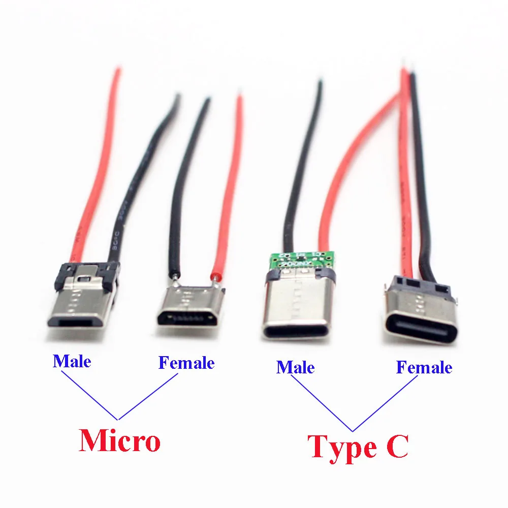
The product images clearly display both Micro USB and USB-C connector types, available in male and female configurations. Each connector is pre-wired with two conductors: a red wire for positive voltage and a black wire for ground. The visible wire length is approximately 7cm. This standardized color coding is crucial for correct polarity.
This pre-wired configuration significantly reduces the complexity and time required for integration into circuit boards or custom enclosures. Users can directly solder these wires to their power rails, bypassing the intricate process of soldering directly onto the tiny connector pins. This simplifies assembly. It also minimizes the risk of cold solder joints on the connector itself.
Unlike raw, un-wired connectors that demand precise micro-soldering skills and specialized tools, these pre-assembled units offer a plug-and-play convenience for power applications. This makes them a superior choice for rapid prototyping or small-scale production where efficiency is paramount. They save considerable effort.
The inclusion of both Micro USB and USB-C options addresses a wide spectrum of project needs. Micro USB remains prevalent in many existing devices, making its inclusion practical for repairs or compatibility with older peripherals. Its widespread adoption means many users still rely on it.
Conversely, the USB-C connectors represent a forward-looking approach. USB-C is the modern standard for power and data, known for its reversible design and higher power delivery capabilities compared to Micro USB. The 2-pin configuration here focuses solely on power. This ensures broad compatibility with newer power sources.
Integrating USB-C into DIY projects allows for compatibility with contemporary power adapters and devices. This future-proofs designs to some extent, as Micro USB is gradually being phased out. The reversible nature of USB-C also enhances user convenience, eliminating frustrating attempts to plug in connectors incorrectly. This improves user experience.
The visible wire gauge appears to be relatively thin, consistent with what is typically found in standard USB charging cables. While no explicit gauge is stated, the visual suggests a range suitable for low-to-moderate current applications. The insulation on the wires is basic, indicating standard voltage handling. This is a critical observation.
This wire gauge implies a practical current limit. For typical 5V USB charging, these connectors are likely adequate for currents up to 2-3 Amperes. Exceeding this range could lead to resistive heating in the wires, potentially compromising insulation integrity. Careful load assessment is critical. Overcurrent can cause significant damage.
Compared to heavy-duty power connectors designed for high-current applications, these units are optimized for compact size and ease of integration in consumer electronics. They are not intended for power delivery systems requiring several tens of amperes, which would necessitate much thicker conductors and more robust insulation. Always verify current ratings.
Wire gauge, often measured by American Wire Gauge (AWG), directly correlates with a wire's current carrying capacity. A smaller AWG number indicates a thicker wire, capable of safely handling more current. The thin wires observed here suggest a higher AWG number. This is a fundamental electrical principle.
Using a wire with insufficient gauge for a given current can result in several hazardous conditions. The wire will heat up due to increased resistance, potentially melting its insulation, causing short circuits, or even initiating a fire. This is a serious safety concern. Proper wire selection prevents these risks.
Unlike applications requiring high-power delivery, such as charging laptops or powering motors, these connectors are best suited for devices like smartphones, small sensors, or LED strips. For these lower power demands, the visible wire gauge is generally acceptable, provided the current draw remains within safe limits. Always calculate your power needs.
The connectors exhibit a compact form factor, with the Micro USB variants showing the familiar trapezoidal shape and the USB-C connectors featuring the reversible oval design. The "Horizontal / Vertical" descriptor in the product title suggests adaptability in mounting, though the images primarily show a horizontal orientation for the pre-wired units. Their small size is a key feature.
The small physical size of these connectors makes them ideal for projects with tight space constraints, such as wearable electronics, miniature IoT devices, or custom power banks. Their low profile allows for discreet integration. This compact nature is a key advantage. It enables sleek product designs.
Many off-the-shelf USB cables come with bulky overmolded connectors that are difficult to integrate into custom enclosures. These bare, pre-wired connectors offer a significant advantage by providing the core functionality without the unnecessary bulk, allowing for cleaner and more professional-looking DIY projects. They simplify enclosure design.
The mention of "Horizontal / Vertical" orientation in the product description is significant for PCB (Printed Circuit Board) design. A horizontal connector lies flat on the board, while a vertical connector stands upright. This choice impacts the overall height and footprint of the final product.
For projects where vertical clearance is limited, a horizontal connector is preferred. Conversely, if board space is at a premium but height is not an issue, a vertical connector can save valuable surface area. The pre-wired nature of these connectors means the orientation primarily refers to how the connector body itself would be mounted if soldered directly to a PCB. This offers design flexibility.
Unlike fixed-orientation panel-mount connectors, these small, wired units provide more freedom in how they are positioned within an enclosure. The wires allow for routing the connector to an optimal location, even if it's not directly on the main PCB. This adaptability is highly beneficial for custom builds.
The connectors feature exposed solder points where the wires attach to the connector's internal pins. The wires themselves have standard red and black insulation. No explicit UL or CE markings are visible on the connectors or wires. This lack of visible certification requires user diligence.
The exposed solder points necessitate proper insulation after installation to prevent accidental short circuits, especially in metallic enclosures or where components might shift. Without visible safety certifications, the user assumes responsibility for verifying the suitability of these components for their specific application and ensuring compliance with local electrical codes. Safety is paramount. Proper insulation is non-negotiable.
Unlike fully enclosed, certified power modules, these raw components require the user to implement their own safety measures. This trade-off provides flexibility for custom designs but places the onus of electrical safety squarely on the builder. Always double-check connections. Electrical safety is a serious matter.
Correct wire polarity is absolutely critical when working with these 2-pin connectors. The red wire consistently denotes the positive voltage, and the black wire represents the ground or negative terminal. Reversing this polarity can have severe consequences for connected electronic devices.
Connecting a device with reversed polarity can instantly damage sensitive integrated circuits, microcontrollers, or power management units. This often results in irreversible component failure, rendering the device inoperable. A simple mistake can be costly. Always verify with a multimeter.
Unlike AC power connections where polarity might be less critical for some devices, DC power systems, especially those found in USB-powered electronics, are highly sensitive to correct polarity. Adhering to the red for positive and black for ground convention is not merely a suggestion; it is a fundamental requirement for safe and functional operation. This prevents component destruction.
The product is offered in packs of 2 or 5 pieces, suggesting a focus on bulk purchasing for hobbyists or small-scale manufacturers. The price point is very low, indicating a cost-effective solution for component sourcing. This makes them accessible.
This affordability makes the connectors highly attractive for prototyping where multiple iterations might be required, or for educational purposes where budget constraints are common. The low cost per unit allows for experimentation without significant financial outlay. This reduces project overhead. It encourages innovation.
Purchasing individual, specialized connectors from industrial suppliers can be significantly more expensive. These multi-pack options provide a practical and economical alternative for projects that do not demand industrial-grade specifications or extreme environmental resilience. They offer excellent value.
While the initial cost of these connectors is low, their true value lies in the time and labor savings they provide. The pre-soldered wires eliminate the need for intricate, often frustrating, manual soldering of tiny pins. This translates directly into reduced assembly time.
For a hobbyist, this means more time spent on design and less on repetitive, delicate soldering tasks. For a small business, it means faster production cycles and lower labor costs per unit. The efficiency gain is substantial. Time is money in any project.
Unlike sourcing raw connectors and wires separately, then spending time stripping, tinning, and soldering each connection, these units arrive ready for integration. This streamlined approach ensures projects progress more smoothly and reach completion faster, offering a significant return on investment in terms of saved effort. This is a smart choice for efficiency.
Imagine completing your custom power bank or smart home sensor with a clean, reliable power input, knowing that the connections are secure and efficient. Envision the satisfaction of powering your latest creation with a modern USB-C port, seamlessly integrating it into your existing ecosystem of devices. These connectors provide the foundational reliability needed to bring those innovative projects to life, ensuring consistent power delivery and a professional finish. They empower creators to focus on innovation, not tedious wiring.
Connectivity Essentials: Bridging Power Standards
The product images clearly display both Micro USB and USB-C connector types, available in male and female configurations. Each connector is pre-wired with two conductors: a red wire for positive voltage and a black wire for ground. The visible wire length is approximately 7cm. This standardized color coding is crucial for correct polarity.
This pre-wired configuration significantly reduces the complexity and time required for integration into circuit boards or custom enclosures. Users can directly solder these wires to their power rails, bypassing the intricate process of soldering directly onto the tiny connector pins. This simplifies assembly. It also minimizes the risk of cold solder joints on the connector itself.
Unlike raw, un-wired connectors that demand precise micro-soldering skills and specialized tools, these pre-assembled units offer a plug-and-play convenience for power applications. This makes them a superior choice for rapid prototyping or small-scale production where efficiency is paramount. They save considerable effort.
Micro USB Legacy and USB-C Modernity
The inclusion of both Micro USB and USB-C options addresses a wide spectrum of project needs. Micro USB remains prevalent in many existing devices, making its inclusion practical for repairs or compatibility with older peripherals. Its widespread adoption means many users still rely on it.
Conversely, the USB-C connectors represent a forward-looking approach. USB-C is the modern standard for power and data, known for its reversible design and higher power delivery capabilities compared to Micro USB. The 2-pin configuration here focuses solely on power. This ensures broad compatibility with newer power sources.
Integrating USB-C into DIY projects allows for compatibility with contemporary power adapters and devices. This future-proofs designs to some extent, as Micro USB is gradually being phased out. The reversible nature of USB-C also enhances user convenience, eliminating frustrating attempts to plug in connectors incorrectly. This improves user experience.
Electrical Integrity: Assessing Current Pathways
The visible wire gauge appears to be relatively thin, consistent with what is typically found in standard USB charging cables. While no explicit gauge is stated, the visual suggests a range suitable for low-to-moderate current applications. The insulation on the wires is basic, indicating standard voltage handling. This is a critical observation.
This wire gauge implies a practical current limit. For typical 5V USB charging, these connectors are likely adequate for currents up to 2-3 Amperes. Exceeding this range could lead to resistive heating in the wires, potentially compromising insulation integrity. Careful load assessment is critical. Overcurrent can cause significant damage.
Compared to heavy-duty power connectors designed for high-current applications, these units are optimized for compact size and ease of integration in consumer electronics. They are not intended for power delivery systems requiring several tens of amperes, which would necessitate much thicker conductors and more robust insulation. Always verify current ratings.
The Importance of Wire Gauge
Wire gauge, often measured by American Wire Gauge (AWG), directly correlates with a wire's current carrying capacity. A smaller AWG number indicates a thicker wire, capable of safely handling more current. The thin wires observed here suggest a higher AWG number. This is a fundamental electrical principle.
Using a wire with insufficient gauge for a given current can result in several hazardous conditions. The wire will heat up due to increased resistance, potentially melting its insulation, causing short circuits, or even initiating a fire. This is a serious safety concern. Proper wire selection prevents these risks.
Unlike applications requiring high-power delivery, such as charging laptops or powering motors, these connectors are best suited for devices like smartphones, small sensors, or LED strips. For these lower power demands, the visible wire gauge is generally acceptable, provided the current draw remains within safe limits. Always calculate your power needs.
Design and Integration: Form Factor and Mounting Flexibility
The connectors exhibit a compact form factor, with the Micro USB variants showing the familiar trapezoidal shape and the USB-C connectors featuring the reversible oval design. The "Horizontal / Vertical" descriptor in the product title suggests adaptability in mounting, though the images primarily show a horizontal orientation for the pre-wired units. Their small size is a key feature.
The small physical size of these connectors makes them ideal for projects with tight space constraints, such as wearable electronics, miniature IoT devices, or custom power banks. Their low profile allows for discreet integration. This compact nature is a key advantage. It enables sleek product designs.
Many off-the-shelf USB cables come with bulky overmolded connectors that are difficult to integrate into custom enclosures. These bare, pre-wired connectors offer a significant advantage by providing the core functionality without the unnecessary bulk, allowing for cleaner and more professional-looking DIY projects. They simplify enclosure design.
Connector Orientation and Board Integration
The mention of "Horizontal / Vertical" orientation in the product description is significant for PCB (Printed Circuit Board) design. A horizontal connector lies flat on the board, while a vertical connector stands upright. This choice impacts the overall height and footprint of the final product.
For projects where vertical clearance is limited, a horizontal connector is preferred. Conversely, if board space is at a premium but height is not an issue, a vertical connector can save valuable surface area. The pre-wired nature of these connectors means the orientation primarily refers to how the connector body itself would be mounted if soldered directly to a PCB. This offers design flexibility.
Unlike fixed-orientation panel-mount connectors, these small, wired units provide more freedom in how they are positioned within an enclosure. The wires allow for routing the connector to an optimal location, even if it's not directly on the main PCB. This adaptability is highly beneficial for custom builds.
Safety Protocols: Mitigating Electrical Risks
The connectors feature exposed solder points where the wires attach to the connector's internal pins. The wires themselves have standard red and black insulation. No explicit UL or CE markings are visible on the connectors or wires. This lack of visible certification requires user diligence.
The exposed solder points necessitate proper insulation after installation to prevent accidental short circuits, especially in metallic enclosures or where components might shift. Without visible safety certifications, the user assumes responsibility for verifying the suitability of these components for their specific application and ensuring compliance with local electrical codes. Safety is paramount. Proper insulation is non-negotiable.
Unlike fully enclosed, certified power modules, these raw components require the user to implement their own safety measures. This trade-off provides flexibility for custom designs but places the onus of electrical safety squarely on the builder. Always double-check connections. Electrical safety is a serious matter.
The Criticality of Proper Polarity
Correct wire polarity is absolutely critical when working with these 2-pin connectors. The red wire consistently denotes the positive voltage, and the black wire represents the ground or negative terminal. Reversing this polarity can have severe consequences for connected electronic devices.
Connecting a device with reversed polarity can instantly damage sensitive integrated circuits, microcontrollers, or power management units. This often results in irreversible component failure, rendering the device inoperable. A simple mistake can be costly. Always verify with a multimeter.
Unlike AC power connections where polarity might be less critical for some devices, DC power systems, especially those found in USB-powered electronics, are highly sensitive to correct polarity. Adhering to the red for positive and black for ground convention is not merely a suggestion; it is a fundamental requirement for safe and functional operation. This prevents component destruction.
Value Proposition: Maximizing Project Efficiency
The product is offered in packs of 2 or 5 pieces, suggesting a focus on bulk purchasing for hobbyists or small-scale manufacturers. The price point is very low, indicating a cost-effective solution for component sourcing. This makes them accessible.
This affordability makes the connectors highly attractive for prototyping where multiple iterations might be required, or for educational purposes where budget constraints are common. The low cost per unit allows for experimentation without significant financial outlay. This reduces project overhead. It encourages innovation.
Purchasing individual, specialized connectors from industrial suppliers can be significantly more expensive. These multi-pack options provide a practical and economical alternative for projects that do not demand industrial-grade specifications or extreme environmental resilience. They offer excellent value.
The Long-Term Savings of Pre-Wired Components
While the initial cost of these connectors is low, their true value lies in the time and labor savings they provide. The pre-soldered wires eliminate the need for intricate, often frustrating, manual soldering of tiny pins. This translates directly into reduced assembly time.
For a hobbyist, this means more time spent on design and less on repetitive, delicate soldering tasks. For a small business, it means faster production cycles and lower labor costs per unit. The efficiency gain is substantial. Time is money in any project.
Unlike sourcing raw connectors and wires separately, then spending time stripping, tinning, and soldering each connection, these units arrive ready for integration. This streamlined approach ensures projects progress more smoothly and reach completion faster, offering a significant return on investment in terms of saved effort. This is a smart choice for efficiency.
Imagine completing your custom power bank or smart home sensor with a clean, reliable power input, knowing that the connections are secure and efficient. Envision the satisfaction of powering your latest creation with a modern USB-C port, seamlessly integrating it into your existing ecosystem of devices. These connectors provide the foundational reliability needed to bring those innovative projects to life, ensuring consistent power delivery and a professional finish. They empower creators to focus on innovation, not tedious wiring.