Multi-Pitch Double Row Male Pin Headers for PCB
Official Store Deal
Expert Analysis Overview
Precision Interconnection Engineering
The Multi-Pitch Double Row Male Pin Headers are essential interconnect components designed for robust and flexible PCB prototyping and production. This assessment is based on the visible range of pitches and configurations, indicating a product engineered for broad compatibility in electronic assembly. The inclusion of multiple standard pitches directly addresses a common challenge in electrical design.Pitch Versatility and Application
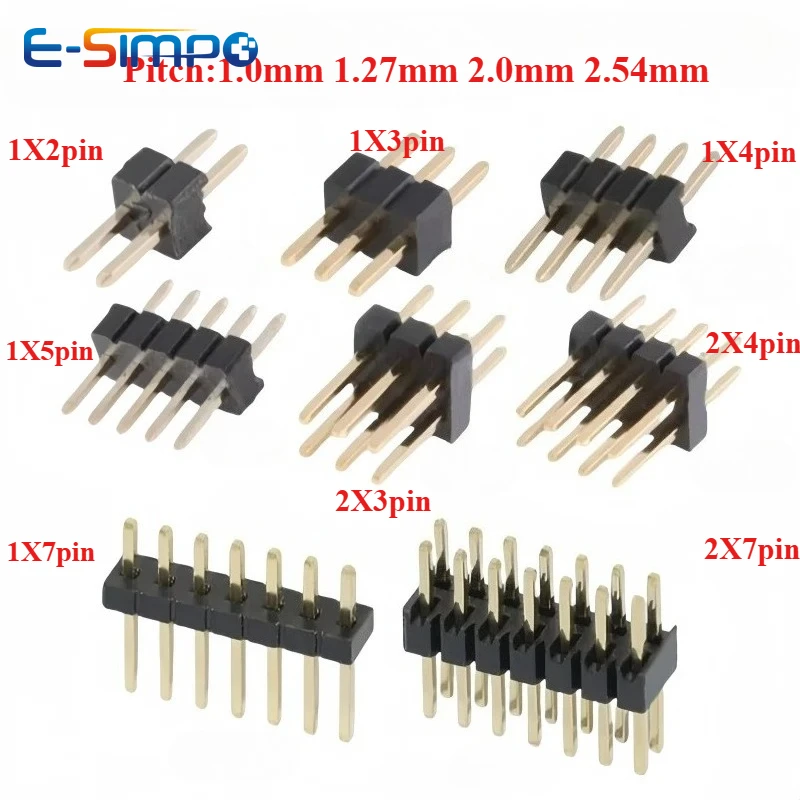
The most striking feature of these pin headers is their comprehensive range of pitches: 1.0mm, 1.27mm, 2.0mm, and 2.54mm. This versatility is not merely a convenience; it is a critical engineering advantage in a world where electronic components adhere to diverse dimensional standards. Different microcontrollers, memory modules, and display interfaces often utilize specific pitch requirements. A single inventory of these headers can support numerous projects. This reduces the need for specialized stock.Consider a scenario where a designer integrates a compact sensor module with a 1.27mm pitch into a main board designed for 2.54mm components. Without these multi-pitch options, a custom adapter board, a different header type, or even a complete redesign of the module interface would be necessary, adding significant complexity, cost, and development time. These headers simplify the process. They bridge compatibility gaps effectively. The 1.0mm pitch, for instance, is increasingly common in miniaturized IoT devices, while 2.54mm remains the staple for breadboarding and larger development boards like Arduino. This product caters to a wide spectrum.
Unlike generic fixed-pitch headers that force designers into specific component choices or require extensive inventory management, this selection allows engineers to maintain a lean inventory while ensuring compatibility across a diverse array of integrated circuits, development boards, and custom PCB layouts. This flexibility is paramount for rapid prototyping environments where component specifications can change frequently during the iterative design process. It streamlines the design workflow. The ability to quickly adapt to varying component footprints accelerates development.
Material Integrity and Conductivity
The visual evidence suggests a construction featuring gold-colored pins and a black plastic insulator. Gold plating on electrical contacts is a standard practice for enhancing conductivity and corrosion resistance. This is a critical factor for long-term reliability in any electronic system. The thin, durable gold layer effectively prevents oxidation and sulfidation, which can lead to increased contact resistance and signal degradation over time. This ensures stable electrical performance.In practical applications, especially in environments with fluctuating humidity, temperature, or the presence of airborne contaminants, the integrity of electrical contacts is paramount. Oxidized or corroded pins can introduce noise into sensitive analog or high-speed digital circuits, cause intermittent failures in power delivery, or even lead to complete circuit malfunction. Gold plating mitigates these risks. It ensures consistent electrical performance. The low contact resistance of gold is particularly beneficial for low-voltage, low-current signal lines where even minor resistance increases can impact data integrity.
Compared to tin-plated alternatives, which are more susceptible to fretting corrosion (wear-induced oxidation) and whisker growth, gold-plated pins offer superior durability and contact reliability, particularly in applications requiring frequent mating and unmating cycles. While tin is more cost-effective for static, high-current connections, its limitations make gold a preferred choice for critical signal and data connections. This is a wise material choice. The black plastic insulator, likely PBT (Polybutylene Terephthalate) or Nylon, provides excellent dielectric strength and mechanical stability, resisting common solvents and moderate temperatures.
Structural Design for Reliability
The double-row male configuration provides a more stable and secure connection compared to single-row headers. This increased mechanical stability is beneficial for modules that might experience vibration, require a robust physical interface, or need to withstand repeated insertions and removals. More pins mean more surface area. The dual rows distribute mechanical stress more evenly, reducing the likelihood of pins bending or the header rocking within its socket.Furthermore, the "breakaway" design is a significant practical advantage for custom applications. It allows users to snap the header strip to the exact number of pins required for a specific application, from a 1x2 configuration up to a 1x40 or 2x40. This eliminates waste and provides precise customization. It is highly adaptable. The scoring lines on the plastic insulator facilitate clean breaks, ensuring that the remaining pins are still usable and structurally sound.
This design contrasts sharply with fixed-length headers, which often result in unused pins being cut off crudely, potentially damaging the remaining pins, or requiring the purchase of multiple distinct header types for different pin counts. The ability to customize pin count on-site reduces project lead times and simplifies component management. It offers unparalleled flexibility. This modularity is a boon for both hobbyists and professional engineers working on diverse projects.
Installation and Safety Protocols
Proper installation of pin headers is as crucial as their inherent quality. The electrical integrity and long-term reliability of a circuit rely heavily on sound mechanical and electrical connections. Attention to detail prevents failures. Adherence to best practices is essential.Proper Soldering Techniques
When integrating these pin headers into a PCB, correct soldering technique is non-negotiable for ensuring reliable electrical and mechanical bonds. The pins must be adequately heated to allow the solder to flow smoothly and create a strong metallurgical bond with the PCB pad. Cold solder joints, characterized by a dull, grainy appearance and poor wetting, are a common cause of intermittent connections, high resistance, and circuit failures. Use proper heat. Insufficient heat can lead to a weak bond, while excessive heat can damage the plastic insulator or the PCB itself.For the smaller 1.0mm and 1.27mm pitches, precision soldering equipment, such as fine-tipped soldering irons, high-quality flux, and possibly magnification, becomes essential. The close proximity of pins increases the risk of solder bridges, which can create unintended short circuits between adjacent pins, leading to component damage or system malfunction. Careful application of solder is vital. Post-solder inspection under magnification is highly recommended to identify and correct any potential issues before power is applied.
Unlike larger 2.54mm pitch components where minor imperfections might be more forgiving due to greater spacing, the tighter tolerances of micro-pitch headers demand meticulous attention to detail. A well-executed solder joint ensures both mechanical stability and optimal electrical conductivity, preventing future troubleshooting headaches and ensuring the longevity of the electronic assembly. This guarantees circuit reliability. Proper ventilation is also critical during soldering to protect respiratory health.
Load Capacity Considerations
While these pin headers are designed for general-purpose use, understanding their current carrying capacity is critical for safety and system stability. The typical current rating for such pins, especially with gold plating, generally ranges from 1 to 3 Amperes per pin, suitable for signal and low-power applications. Exceeding this limit can lead to excessive heat generation within the pin and its surrounding insulator. Overheating is a serious concern.Sustained overcurrent can degrade the plastic insulator, potentially leading to melting, deformation, or even fire, especially if multiple adjacent pins are simultaneously overloaded. It can also damage the PCB traces connected to the header and the components drawing power through it. Always calculate the maximum expected current for each pin in your design. Verify the circuit demands against the component specifications.
Unlike power connectors designed for high amperage, which feature larger contact areas, thicker conductors, and often specialized high-temperature insulators, these signal and low-power headers are not intended for heavy current loads. For applications requiring higher current, dedicated power connectors with appropriate gauge wiring and robust insulation are necessary to prevent thermal runaway and ensure compliance with electrical safety standards. Safety must be prioritized.
Environmental Durability
The black plastic insulator, typically PBT or Nylon, offers good mechanical strength and electrical insulation properties under typical operating conditions. However, its thermal limits must be respected. Most standard plastic headers are rated for operating temperatures up to approximately 105°C. Exceeding this temperature can compromise its structural integrity, leading to softening, warping, or embrittlement.Exposure to harsh chemicals, prolonged direct UV radiation, or extreme mechanical stress can also degrade the plastic, leading to brittleness, discoloration, or loss of insulating properties over time. While these headers are generally robust for indoor electronic applications, their suitability for outdoor, automotive, or industrial environments with extreme conditions should be carefully evaluated. Consider the operating environment. Protection from direct sunlight and corrosive agents is advisable.
Compared to specialized industrial-grade connectors with enhanced environmental sealing (e.g., IP-rated), UV-resistant plastics, and wider operating temperature ranges, these general-purpose headers are best suited for controlled environments. Understanding these limitations prevents premature component failure, ensures long-term system stability, and avoids costly replacements or repairs. This extends product lifespan.
Long-Term System Integration
The true value of well-chosen components manifests in the long-term reliability, maintainability, and overall performance of an electronic system. These headers contribute significantly to that goal by providing a dependable interface.Preventing Common Failures
The gold plating on the pins is a key feature in preventing common electrical failures related to oxidation, fretting corrosion, and poor contact. Over time, even in relatively clean environments, exposed metal surfaces can tarnish, especially if they are not gold-plated. This degrades performance. The gold layer acts as a protective barrier.Intermittent connections, often difficult to diagnose and frustrating to troubleshoot, can frequently be traced back to compromised contact surfaces or micro-movements causing wear. The robust gold plating ensures that the electrical path remains clear and low-resistance throughout the product's lifespan, even after multiple mating cycles. This minimizes troubleshooting efforts. It enhances signal integrity.
Unlike unplated or poorly plated pins that might require periodic cleaning, application of contact enhancers, or premature replacement, these gold-plated headers offer a "set-and-forget" reliability for their intended applications. This reduces maintenance overhead, improves system uptime, and contributes to the overall robustness of the electronic assembly. It is a smart investment. The consistency of connection is paramount.
Value Proposition for Engineers
For electrical engineers, product developers, and hobbyists alike, these multi-pitch, double-row breakaway pin headers represent a significant value proposition. They streamline the component selection process, reduce inventory complexity, and offer unparalleled design flexibility. Fewer parts to manage. This consolidation of functionality into a single product type simplifies procurement.The ability to adapt a single product to various pitch requirements means less time spent sourcing specific connectors for each unique board or module, and more time focused on core design and functionality. This efficiency translates directly into faster development cycles, reduced project costs, and quicker time-to-market for new products. Time is money in engineering. This versatility is a competitive edge.
Instead of purchasing multiple distinct header types in various lengths and pitches, a bulk pack of these versatile connectors provides a comprehensive solution for a wide array of prototyping and production needs. This strategic acquisition prevents project delays due to incompatible components and ensures that the right connector is always on hand. It is a versatile toolkit staple. This approach optimizes resource allocation.
Imagine completing a complex PCB assembly without encountering a single component compatibility issue, knowing that every connection is secure, optimized for signal integrity, and built to last. These pin headers contribute to that seamless experience, allowing engineers to focus on innovation rather than basic connectivity challenges. They empower efficient design. Their adaptability makes them an indispensable asset for any electronics workbench, ensuring projects proceed smoothly and reliably from concept to completion.