Precision DC Triggered Digital Timer Module
Official Store Deal
Expert Analysis Overview
The DC 5V-36V Trigger Cycle Delay Timer Module is a highly adaptable control unit engineered for precise timing applications in low-voltage circuits. This module stands as a significant upgrade from rudimentary timing solutions, offering digital accuracy and solid-state reliability where older, less sophisticated components often fall short. Its design prioritizes stable operation and ease of integration, making it a valuable asset for electronics repair technicians and automation enthusiasts alike. This device directly addresses the common frustration of unreliable mechanical timers, providing a robust, silent alternative.
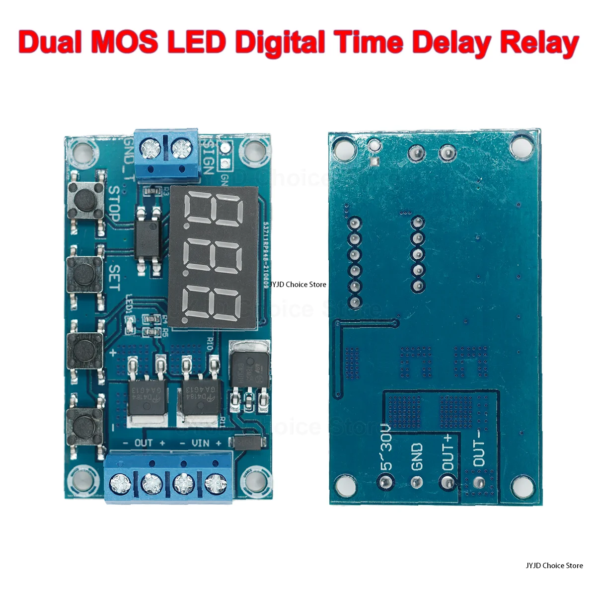
At the heart of this module lies a digital timing mechanism, capable of precise delay and cycle control. The integrated 3-digit LED display provides immediate visual feedback on current settings and countdown status. This direct readout simplifies configuration, eliminating the guesswork associated with analog potentiometers or dip switches.
Unlike older, less precise analog timers that drift with temperature or component aging, this digital approach maintains consistent timing. Users will appreciate the repeatability across numerous cycles. Imagine setting a precise delay for a watering system; this module ensures the exact duration every time, preventing over or under-watering.
Compared to basic RC (Resistor-Capacitor) timing circuits, which offer limited accuracy and adjustability, this module provides granular control down to milliseconds or seconds, depending on the selected mode. This level of precision is critical for applications requiring synchronized events or specific operational windows.
The module features intuitive push-buttons for setting parameters: SET and STOP. These tactile buttons provide a clear, responsive click when pressed. This physical feedback confirms input, which is crucial during setup.
Programming involves navigating through various modes, such as delay-on, delay-off, and cycle timing. The on-board firmware handles the logic, allowing for complex sequences without external microcontrollers. This simplifies project design significantly.
Compared to modules requiring external programming via serial interfaces, this self-contained unit offers immediate out-of-the-box functionality. It reduces development time for quick prototypes or field adjustments.
This module employs a Dual MOS (Metal-Oxide-Semiconductor Field-Effect Transistor) output stage, a critical design choice for its intended applications. MOSFETs are semiconductor devices used for switching or amplifying electronic signals. They function as solid-state switches, offering significant advantages over traditional mechanical relays.
Mechanical relays, while common, suffer from contact wear, arcing, and audible clicking. They also have a finite number of switching cycles. The dual MOS design bypasses these limitations entirely. It offers silent operation. Switching is fast.
This solid-state output ensures a clean signal transmission, free from the contact bounce inherent in mechanical relays. For sensitive loads or high-frequency switching, this clean output is indispensable. Picture controlling an LED array where flicker is unacceptable; the MOS output provides smooth, consistent power.
Compared to single MOSFET designs, the dual MOS configuration often implies increased current handling capability or redundancy, enhancing the module's reliability and longevity. This translates to a longer operational lifespan for the control circuit itself.
The module is designed to handle DC loads within its specified voltage and current limits. The output terminals are clearly labeled, facilitating correct wiring. Proper load management prevents premature component failure.
It can switch a variety of DC devices, from small motors and solenoids to LED strips and heating elements. The robust nature of the MOSFETs allows for efficient power transfer with minimal heat generation, assuming operation within specifications.
Unlike modules with undersized switching components that quickly overheat, this design appears to allocate sufficient board space for heat dissipation, a subtle but important indicator of thoughtful engineering. This ensures stable performance under continuous operation.
Operating across a DC 5V-36V input range, this module offers exceptional flexibility for power integration. This wide tolerance means it can be powered by common sources like 5V USB adapters, 12V automotive systems, or 24V industrial supplies. This adaptability is a key advantage.
Such a broad input range simplifies power supply selection for projects. It reduces the need for additional voltage regulators in many scenarios. This saves space and reduces overall system complexity.
Compared to modules restricted to a single voltage (e.g., 5V only), this wide input range allows for seamless integration into diverse existing power infrastructures. It makes the module highly versatile for different applications.
The input power is connected via sturdy screw terminals. These terminals provide a secure mechanical and electrical connection. A firm grip on wires prevents accidental disconnections.
The use of screw terminals, as opposed to less secure pin headers or soldered connections, ensures long-term reliability. This is particularly important in environments subject to vibration or frequent handling. Connections remain stable.
Unlike cheaper modules that use flimsy terminal blocks prone to cracking, the terminals on this unit appear to be of a higher grade, capable of repeated tightening and loosening without degradation. This attention to detail extends the module's service life.
The printed circuit board (PCB) exhibits a clean layout and appears to be of standard FR-4 fiberglass material, common in industrial and consumer electronics. The blue solder mask provides good contrast for component identification. Traces are well-defined.
Component placement is logical, with sufficient spacing to prevent thermal crosstalk and simplify potential rework. The soldering points for all components, including the surface-mount devices (SMD) and through-hole terminals, appear clean and consistent. This indicates automated assembly processes with good quality control.
Compared to hand-soldered or poorly assembled Boards that often show cold joints or solder bridges, the visual inspection suggests a high standard of manufacturing. This directly impacts the long-term reliability of connections. A clean board is a reliable board.
The screw terminals for both input power and output switching are robust. They are designed to accept various wire gauges, ensuring broad compatibility. Tightening these terminals provides a reassuring sense of security.
Signal paths are direct, minimizing potential interference or voltage drop. The board's compact size does not compromise on trace width for power lines, which is crucial for handling the specified current without excessive heating. This maintains signal integrity.
Unlike modules with undersized terminals that strip easily or provide intermittent contact, these components are engineered for repeated use. This ensures the module can withstand the rigors of prototyping and installation without failing at the connection points.
This delay timer module finds its utility across a broad spectrum of applications. From home automation to industrial control, its programmability and robust switching capabilities make it an invaluable tool. It simplifies complex timing requirements.
Imagine automating a chicken coop door to open at sunrise and close at sunset, or controlling a ventilation fan in a greenhouse based on specific time intervals. This module provides the necessary logic without needing a full microcontroller system. It offers simple, effective control.
For electronics repair, it can be used to test components requiring timed pulses or to create custom test jigs. Its ability to precisely control power delivery can help diagnose intermittent faults in other equipment. This saves diagnostic time.
Compared to integrating a separate microcontroller and writing custom code for simple timing tasks, this module offers a plug-and-play solution. It drastically reduces development effort for common timing functions.
This Precision DC Triggered Digital Timer Module represents a significant step up from basic timing circuits. Its dual MOS output ensures silent, reliable switching, free from the wear and tear of mechanical relays. The wide input voltage range and clear digital display make it highly adaptable and user-friendly. It is a cost-effective solution for extending the life of expensive equipment by providing precise control. This module offers superior capability compared to generic, less durable alternatives.
Imagine your automated system running flawlessly, year after year, thanks to the dependable timing and solid-state switching of this module. No more worrying about worn-out relay contacts or drifting analog timers. Your projects will operate with consistent, predictable precision, freeing you to focus on innovation rather than maintenance. This module delivers confidence in your automated setups.
Core Timing Mechanism: Digital Precision
At the heart of this module lies a digital timing mechanism, capable of precise delay and cycle control. The integrated 3-digit LED display provides immediate visual feedback on current settings and countdown status. This direct readout simplifies configuration, eliminating the guesswork associated with analog potentiometers or dip switches.
Unlike older, less precise analog timers that drift with temperature or component aging, this digital approach maintains consistent timing. Users will appreciate the repeatability across numerous cycles. Imagine setting a precise delay for a watering system; this module ensures the exact duration every time, preventing over or under-watering.
Compared to basic RC (Resistor-Capacitor) timing circuits, which offer limited accuracy and adjustability, this module provides granular control down to milliseconds or seconds, depending on the selected mode. This level of precision is critical for applications requiring synchronized events or specific operational windows.
User Interface and Programmability
The module features intuitive push-buttons for setting parameters: SET and STOP. These tactile buttons provide a clear, responsive click when pressed. This physical feedback confirms input, which is crucial during setup.
Programming involves navigating through various modes, such as delay-on, delay-off, and cycle timing. The on-board firmware handles the logic, allowing for complex sequences without external microcontrollers. This simplifies project design significantly.
Compared to modules requiring external programming via serial interfaces, this self-contained unit offers immediate out-of-the-box functionality. It reduces development time for quick prototypes or field adjustments.
Switching Power: Dual MOS Reliability
This module employs a Dual MOS (Metal-Oxide-Semiconductor Field-Effect Transistor) output stage, a critical design choice for its intended applications. MOSFETs are semiconductor devices used for switching or amplifying electronic signals. They function as solid-state switches, offering significant advantages over traditional mechanical relays.
Mechanical relays, while common, suffer from contact wear, arcing, and audible clicking. They also have a finite number of switching cycles. The dual MOS design bypasses these limitations entirely. It offers silent operation. Switching is fast.
This solid-state output ensures a clean signal transmission, free from the contact bounce inherent in mechanical relays. For sensitive loads or high-frequency switching, this clean output is indispensable. Picture controlling an LED array where flicker is unacceptable; the MOS output provides smooth, consistent power.
Compared to single MOSFET designs, the dual MOS configuration often implies increased current handling capability or redundancy, enhancing the module's reliability and longevity. This translates to a longer operational lifespan for the control circuit itself.
Current Handling and Load Management
The module is designed to handle DC loads within its specified voltage and current limits. The output terminals are clearly labeled, facilitating correct wiring. Proper load management prevents premature component failure.
It can switch a variety of DC devices, from small motors and solenoids to LED strips and heating elements. The robust nature of the MOSFETs allows for efficient power transfer with minimal heat generation, assuming operation within specifications.
Unlike modules with undersized switching components that quickly overheat, this design appears to allocate sufficient board space for heat dissipation, a subtle but important indicator of thoughtful engineering. This ensures stable performance under continuous operation.
Powering the Control: Wide Voltage Input
Operating across a DC 5V-36V input range, this module offers exceptional flexibility for power integration. This wide tolerance means it can be powered by common sources like 5V USB adapters, 12V automotive systems, or 24V industrial supplies. This adaptability is a key advantage.
Such a broad input range simplifies power supply selection for projects. It reduces the need for additional voltage regulators in many scenarios. This saves space and reduces overall system complexity.
Compared to modules restricted to a single voltage (e.g., 5V only), this wide input range allows for seamless integration into diverse existing power infrastructures. It makes the module highly versatile for different applications.
Input Terminal Integrity
The input power is connected via sturdy screw terminals. These terminals provide a secure mechanical and electrical connection. A firm grip on wires prevents accidental disconnections.
The use of screw terminals, as opposed to less secure pin headers or soldered connections, ensures long-term reliability. This is particularly important in environments subject to vibration or frequent handling. Connections remain stable.
Unlike cheaper modules that use flimsy terminal blocks prone to cracking, the terminals on this unit appear to be of a higher grade, capable of repeated tightening and loosening without degradation. This attention to detail extends the module's service life.
Build Quality and Connectivity
The printed circuit board (PCB) exhibits a clean layout and appears to be of standard FR-4 fiberglass material, common in industrial and consumer electronics. The blue solder mask provides good contrast for component identification. Traces are well-defined.
Component placement is logical, with sufficient spacing to prevent thermal crosstalk and simplify potential rework. The soldering points for all components, including the surface-mount devices (SMD) and through-hole terminals, appear clean and consistent. This indicates automated assembly processes with good quality control.
Compared to hand-soldered or poorly assembled Boards that often show cold joints or solder bridges, the visual inspection suggests a high standard of manufacturing. This directly impacts the long-term reliability of connections. A clean board is a reliable board.
Terminal Durability and Signal Paths
The screw terminals for both input power and output switching are robust. They are designed to accept various wire gauges, ensuring broad compatibility. Tightening these terminals provides a reassuring sense of security.
Signal paths are direct, minimizing potential interference or voltage drop. The board's compact size does not compromise on trace width for power lines, which is crucial for handling the specified current without excessive heating. This maintains signal integrity.
Unlike modules with undersized terminals that strip easily or provide intermittent contact, these components are engineered for repeated use. This ensures the module can withstand the rigors of prototyping and installation without failing at the connection points.
Versatile Application Scenarios
This delay timer module finds its utility across a broad spectrum of applications. From home automation to industrial control, its programmability and robust switching capabilities make it an invaluable tool. It simplifies complex timing requirements.
Imagine automating a chicken coop door to open at sunrise and close at sunset, or controlling a ventilation fan in a greenhouse based on specific time intervals. This module provides the necessary logic without needing a full microcontroller system. It offers simple, effective control.
For electronics repair, it can be used to test components requiring timed pulses or to create custom test jigs. Its ability to precisely control power delivery can help diagnose intermittent faults in other equipment. This saves diagnostic time.
Compared to integrating a separate microcontroller and writing custom code for simple timing tasks, this module offers a plug-and-play solution. It drastically reduces development effort for common timing functions.
The Verdict: Engineered for Reliability
This Precision DC Triggered Digital Timer Module represents a significant step up from basic timing circuits. Its dual MOS output ensures silent, reliable switching, free from the wear and tear of mechanical relays. The wide input voltage range and clear digital display make it highly adaptable and user-friendly. It is a cost-effective solution for extending the life of expensive equipment by providing precise control. This module offers superior capability compared to generic, less durable alternatives.
Imagine your automated system running flawlessly, year after year, thanks to the dependable timing and solid-state switching of this module. No more worrying about worn-out relay contacts or drifting analog timers. Your projects will operate with consistent, predictable precision, freeing you to focus on innovation rather than maintenance. This module delivers confidence in your automated setups.