RG58 Low Loss 50 Ohm Coaxial Cable
Official Store Deal
Expert Analysis Overview
RG58 50-3 Coaxial Cable is a foundational RF transmission line, critically engineered for reliable signal integrity in diverse communication systems. This cable provides the essential conduit for radio frequency signals, ensuring minimal degradation from source to destination. Its design prioritizes consistent impedance and effective shielding, crucial for sensitive electronic applications. It performs reliably.
The selection of appropriate coaxial cable forms the bedrock of any robust radio frequency system. This RG58 50-3 variant, with its bare copper inner conductor and 50 Ohm characteristic impedance, stands as a workhorse in the electrical landscape. It is a standard choice. Unlike generic wiring, this cable is purpose-built for high-frequency signal transmission, where impedance matching and signal loss are paramount considerations. Improper cable choice can lead to significant signal reflections and power loss, compromising system performance and potentially damaging connected equipment. This must be avoided. The integrity of the entire RF chain hinges on the quality of its cabling.
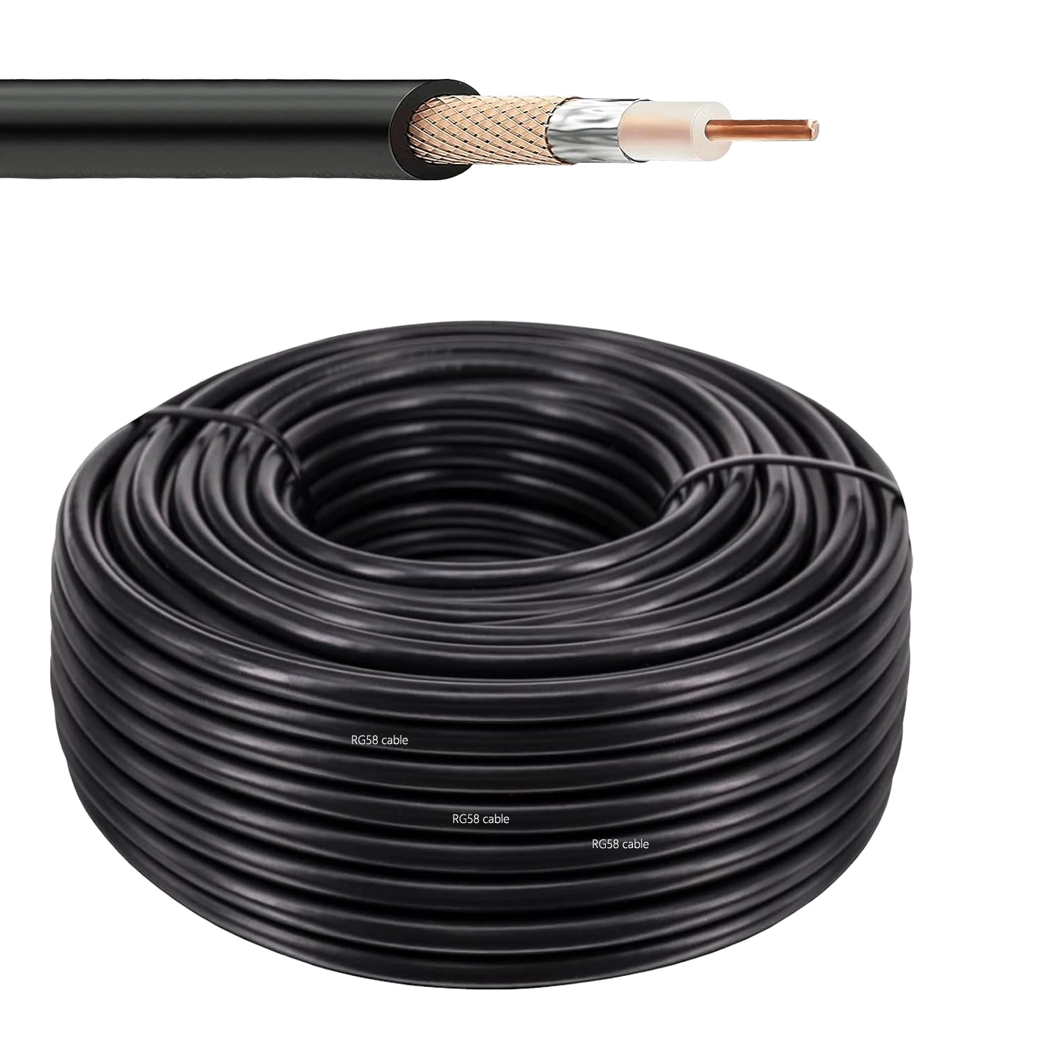
At the core of this RG58 cable lies a bare copper inner conductor. This material choice is not arbitrary. Bare copper offers superior electrical conductivity compared to copper-clad steel (CCS) alternatives, especially at the higher frequencies typical of RF applications. The 0.81 mm diameter conductor ensures a consistent path for the signal. This directly translates to lower signal attenuation over distance. Imagine a clear highway for your data.
When comparing this to standard entry-level coaxial cables, the bare copper core provides a distinct advantage. Many cheaper cables utilize CCS, which, while more rigid and less expensive, exhibits higher resistance and greater signal loss, particularly as frequencies increase. For critical applications like amateur radio, test and measurement, or data links, the investment in bare copper pays dividends in signal clarity and system efficiency. This is a performance upgrade. It is a smart choice. The skin effect, where high-frequency currents tend to flow on the surface of a conductor, makes the conductivity of the outer layer of the inner conductor particularly important. Bare copper excels here.
The physical properties of the inner conductor are paramount. Its uniform diameter and material composition directly influence the cable's characteristic impedance and attenuation. Any inconsistencies can introduce reflections, degrading the signal. This bare copper conductor minimizes such risks. It ensures stable transmission. This attention to core material directly impacts the cable's ability to maintain a clean, strong signal over its entire length, a non-negotiable requirement for professional installations.
Effective shielding is non-negotiable in RF environments. This cable incorporates a tinned copper braid outer conductor, serving as a robust shield against external electromagnetic interference (EMI) and radio frequency interference (RFI). The braid construction provides excellent coverage. This prevents unwanted noise from corrupting the transmitted signal and also minimizes signal leakage from the cable itself. Interference is a problem.
Consider a scenario where sensitive electronic equipment operates in close proximity to power lines or other RF sources. Without adequate shielding, stray electromagnetic fields can induce currents in the cable, leading to distorted signals and unreliable operation. The tinned copper braid acts as a Faraday cage, protecting the inner conductor. This design offers better flexibility and often superior shielding effectiveness across a broad frequency range compared to simple foil shields found in some lower-grade cables. Protection is vital. The tinning on the copper braid also provides corrosion resistance, extending the lifespan and maintaining shielding effectiveness in various environments.
The density and quality of the braid are critical. A high-quality braid, like the tinned copper used here, ensures consistent shielding effectiveness across the cable's length. This directly impacts the signal-to-noise ratio of the transmitted signal. It is a key component. A denser braid offers more points of contact for stray fields, effectively shunting them to ground and preventing them from reaching the signal-carrying core.
A defining characteristic of this RG58 cable is its 50 Ohm characteristic impedance. This value is the industry standard for most RF communication systems, including amateur radio, cellular networks, and many test instruments. Maintaining a consistent 50 Ohm impedance throughout the entire signal path is critical for maximizing power transfer and minimizing signal reflections. Reflections cause standing waves.
When a signal encounters an impedance mismatch, a portion of its energy is reflected back towards the source, leading to reduced power at the load and potential damage to the transmitter. This cable's precise 50 Ohm impedance, maintained by its polyethylene (PE) dielectric and overall construction, ensures optimal power delivery. Unlike 75 Ohm cables, which are designed for video applications, this 50 Ohm cable is specifically tailored for the demands of RF power and data transmission. Match impedance correctly. A standing wave ratio (SWR) of 1:1 is the ideal, indicating perfect impedance matching and maximum power transfer.
The dielectric material, polyethylene (PE), plays a crucial role in maintaining this impedance. Its consistent dielectric constant ensures the capacitance between the inner and outer conductors remains stable. This is fundamental to performance. The uniform thickness and composition of the PE dielectric are precisely controlled during manufacturing to achieve the specified 50 Ohm impedance, a critical factor for high-frequency signal integrity.
The cable's external layer is a durable PVC jacket. This jacket provides essential mechanical protection for the internal components, safeguarding them from abrasion, moisture, and minor impacts. The 4.95 mm outer diameter gives it a substantial feel. While PVC offers good general-purpose protection, it is important to understand its limitations. It protects the core.
For indoor installations or protected outdoor environments, the PVC jacket performs admirably. However, for applications requiring prolonged exposure to harsh UV radiation, extreme temperatures, or aggressive chemicals, specialized jackets like polyethylene (PE) or thermoplastic elastomer (TPE) might be more suitable. The PVC jacket on this RG58 cable is designed for flexibility and ease of installation, with a nominal bend radius of 25 mm, allowing for practical routing without compromising signal integrity. This flexibility is a key advantage. The jacket's resistance to common oils and greases also contributes to its utility in various industrial settings.
The tactile feel of the jacket suggests a balance between protection and pliability. It bends without undue force. This is important for installation in confined spaces. The smooth finish of the PVC jacket also aids in pulling the cable through conduits or cable trays, reducing friction and potential damage during installation.
Understanding signal attenuation is paramount for any RF system designer. The provided specifications detail the nominal attenuation at various frequencies: 0.151 dB/m at 100 MHz, 0.308 dB/m at 400 MHz, and 0.502 dB/m at 1000 MHz. These figures are crucial. These values indicate the signal loss per meter of cable at specific frequencies.
For instance, a 50-meter run of this cable at 400 MHz would incur approximately 15.4 dB of loss (50m * 0.308 dB/m). This information allows electricians and engineers to calculate link budgets accurately, ensuring sufficient signal strength reaches the receiver. Compared to higher-loss cables, this RG58's attenuation characteristics make it suitable for moderate cable runs without requiring excessive amplification, thereby simplifying system design and reducing overall cost. It saves power. The attenuation figures are a direct measure of the cable's efficiency.
The velocity of propagation, listed at 66%, also impacts signal timing. This is a standard value for PE dielectrics. It affects phase relationships. For time-sensitive applications or phased antenna arrays, understanding this parameter is essential for precise system calibration and performance.
The 1400 VMS voltage rating of this RG58 cable provides a significant safety margin for most RF applications. This rating specifies the maximum RMS voltage the cable can safely handle without breakdown. While typical RF power levels in amateur radio or commercial two-way radio systems are often much lower, this high voltage rating ensures robustness against transient spikes and provides peace of mind. Safety is paramount.
This robust voltage handling capability means the cable can reliably transmit signals even when high power levels are involved, without risking insulation breakdown or electrical hazards. It surpasses the requirements of many low-power data and communication links, offering an added layer of reliability. Always confirm the cable's voltage rating meets or exceeds the maximum expected voltage in your specific application to prevent electrical fires and ensure safety standard compliance. Prevent dangerous overloads. This rating is a critical safety specification.
The insulation's integrity is directly tied to this rating. The PE dielectric provides excellent insulating properties. It resists electrical stress. Its ability to withstand high voltages without arcing or breakdown is a testament to its quality and the cable's overall construction.
The product's emphasis on pigtail RF wire connector compatibility for SMA, BNC, N, UHF, and TNC types highlights its versatility. These are common RF connectors. This means the cable can be readily integrated into a wide array of existing and new systems. Each connector type serves specific purposes and frequency ranges.
* SMA connectors are small, threaded connectors often used in Wi-Fi, cellular, and microwave applications up to 18 GHz. They offer secure connections.
* BNC connectors are bayonet-style, quick-disconnect connectors popular in test equipment, video, and lower-frequency RF applications up to 4 GHz. They are fast to connect.
* N connectors are robust, threaded connectors suitable for medium to high-power RF applications up to 11 GHz. They handle significant power.
* UHF connectors (PL-259/SO-239) are older, lower-frequency connectors commonly found in amateur radio and CB radio applications. They are widely used.
* TNC connectors are threaded versions of BNC, offering better vibration resistance and performance at higher frequencies than BNC. They resist vibration well.
The ability to terminate this RG58 cable with such a diverse range of connectors makes it an incredibly adaptable component for any electrician or RF technician. Proper termination is key. Verifying terminal quality, whether factory-installed or field-crimped, is essential for maintaining the cable's low-loss characteristics and impedance matching. Quality connections matter. The visual representation of various connector types alongside the cable underscores its broad applicability. This visual aid clarifies compatibility. It simplifies selection.
Proper installation techniques are crucial for maximizing the lifespan and performance of any coaxial cable. Avoid sharp bends that exceed the nominal bend radius of 25 mm, as this can deform the dielectric and inner conductor, leading to impedance discontinuities and increased signal loss. Secure the cable adequately to prevent strain on connectors and to avoid accidental damage. Damage degrades performance. Cable ties should be used judiciously, avoiding over-tightening which can compress the jacket and alter impedance.
Regular inspection for physical damage, especially in outdoor or high-traffic areas, is recommended. The PVC jacket, while durable, can be compromised by prolonged UV exposure or mechanical stress. Cleaning connector interfaces with appropriate contact cleaner can prevent signal degradation caused by dirt or oxidation. A clean connection is a strong connection. This extends cable life. Proper grounding of the cable shield is also essential for safety and optimal EMI performance.
This RG58 50-3 Coaxial Cable represents a sound choice for professionals and enthusiasts alike who demand dependable RF signal transmission. Its bare copper conductor, effective shielding, and consistent 50 Ohm impedance provide a robust foundation for various communication needs. The availability in multiple lengths (10M, 20M, 50M) ensures flexibility for different project scales. It is a versatile solution.
Imagine completing your next antenna installation or setting up a critical test bench with the confidence that your signal path is optimized for minimal loss and maximum clarity. Picture your amateur radio transmissions reaching further, or your data links operating with unwavering stability. This cable delivers that assurance, allowing you to focus on the performance of your equipment, not the integrity of your wiring. This is true peace of mind. Investing in quality cabling like this reduces troubleshooting time and enhances overall system reliability.
The Backbone of RF Communication
The selection of appropriate coaxial cable forms the bedrock of any robust radio frequency system. This RG58 50-3 variant, with its bare copper inner conductor and 50 Ohm characteristic impedance, stands as a workhorse in the electrical landscape. It is a standard choice. Unlike generic wiring, this cable is purpose-built for high-frequency signal transmission, where impedance matching and signal loss are paramount considerations. Improper cable choice can lead to significant signal reflections and power loss, compromising system performance and potentially damaging connected equipment. This must be avoided. The integrity of the entire RF chain hinges on the quality of its cabling.
Conductor Integrity and Signal Flow
At the core of this RG58 cable lies a bare copper inner conductor. This material choice is not arbitrary. Bare copper offers superior electrical conductivity compared to copper-clad steel (CCS) alternatives, especially at the higher frequencies typical of RF applications. The 0.81 mm diameter conductor ensures a consistent path for the signal. This directly translates to lower signal attenuation over distance. Imagine a clear highway for your data.
When comparing this to standard entry-level coaxial cables, the bare copper core provides a distinct advantage. Many cheaper cables utilize CCS, which, while more rigid and less expensive, exhibits higher resistance and greater signal loss, particularly as frequencies increase. For critical applications like amateur radio, test and measurement, or data links, the investment in bare copper pays dividends in signal clarity and system efficiency. This is a performance upgrade. It is a smart choice. The skin effect, where high-frequency currents tend to flow on the surface of a conductor, makes the conductivity of the outer layer of the inner conductor particularly important. Bare copper excels here.
The physical properties of the inner conductor are paramount. Its uniform diameter and material composition directly influence the cable's characteristic impedance and attenuation. Any inconsistencies can introduce reflections, degrading the signal. This bare copper conductor minimizes such risks. It ensures stable transmission. This attention to core material directly impacts the cable's ability to maintain a clean, strong signal over its entire length, a non-negotiable requirement for professional installations.
Shielding Against Interference
Effective shielding is non-negotiable in RF environments. This cable incorporates a tinned copper braid outer conductor, serving as a robust shield against external electromagnetic interference (EMI) and radio frequency interference (RFI). The braid construction provides excellent coverage. This prevents unwanted noise from corrupting the transmitted signal and also minimizes signal leakage from the cable itself. Interference is a problem.
Consider a scenario where sensitive electronic equipment operates in close proximity to power lines or other RF sources. Without adequate shielding, stray electromagnetic fields can induce currents in the cable, leading to distorted signals and unreliable operation. The tinned copper braid acts as a Faraday cage, protecting the inner conductor. This design offers better flexibility and often superior shielding effectiveness across a broad frequency range compared to simple foil shields found in some lower-grade cables. Protection is vital. The tinning on the copper braid also provides corrosion resistance, extending the lifespan and maintaining shielding effectiveness in various environments.
The density and quality of the braid are critical. A high-quality braid, like the tinned copper used here, ensures consistent shielding effectiveness across the cable's length. This directly impacts the signal-to-noise ratio of the transmitted signal. It is a key component. A denser braid offers more points of contact for stray fields, effectively shunting them to ground and preventing them from reaching the signal-carrying core.
Impedance Matching for Optimal Performance
A defining characteristic of this RG58 cable is its 50 Ohm characteristic impedance. This value is the industry standard for most RF communication systems, including amateur radio, cellular networks, and many test instruments. Maintaining a consistent 50 Ohm impedance throughout the entire signal path is critical for maximizing power transfer and minimizing signal reflections. Reflections cause standing waves.
When a signal encounters an impedance mismatch, a portion of its energy is reflected back towards the source, leading to reduced power at the load and potential damage to the transmitter. This cable's precise 50 Ohm impedance, maintained by its polyethylene (PE) dielectric and overall construction, ensures optimal power delivery. Unlike 75 Ohm cables, which are designed for video applications, this 50 Ohm cable is specifically tailored for the demands of RF power and data transmission. Match impedance correctly. A standing wave ratio (SWR) of 1:1 is the ideal, indicating perfect impedance matching and maximum power transfer.
The dielectric material, polyethylene (PE), plays a crucial role in maintaining this impedance. Its consistent dielectric constant ensures the capacitance between the inner and outer conductors remains stable. This is fundamental to performance. The uniform thickness and composition of the PE dielectric are precisely controlled during manufacturing to achieve the specified 50 Ohm impedance, a critical factor for high-frequency signal integrity.
Durability and Environmental Protection
The cable's external layer is a durable PVC jacket. This jacket provides essential mechanical protection for the internal components, safeguarding them from abrasion, moisture, and minor impacts. The 4.95 mm outer diameter gives it a substantial feel. While PVC offers good general-purpose protection, it is important to understand its limitations. It protects the core.
For indoor installations or protected outdoor environments, the PVC jacket performs admirably. However, for applications requiring prolonged exposure to harsh UV radiation, extreme temperatures, or aggressive chemicals, specialized jackets like polyethylene (PE) or thermoplastic elastomer (TPE) might be more suitable. The PVC jacket on this RG58 cable is designed for flexibility and ease of installation, with a nominal bend radius of 25 mm, allowing for practical routing without compromising signal integrity. This flexibility is a key advantage. The jacket's resistance to common oils and greases also contributes to its utility in various industrial settings.
The tactile feel of the jacket suggests a balance between protection and pliability. It bends without undue force. This is important for installation in confined spaces. The smooth finish of the PVC jacket also aids in pulling the cable through conduits or cable trays, reducing friction and potential damage during installation.
Attenuation and Frequency Response
Understanding signal attenuation is paramount for any RF system designer. The provided specifications detail the nominal attenuation at various frequencies: 0.151 dB/m at 100 MHz, 0.308 dB/m at 400 MHz, and 0.502 dB/m at 1000 MHz. These figures are crucial. These values indicate the signal loss per meter of cable at specific frequencies.
For instance, a 50-meter run of this cable at 400 MHz would incur approximately 15.4 dB of loss (50m * 0.308 dB/m). This information allows electricians and engineers to calculate link budgets accurately, ensuring sufficient signal strength reaches the receiver. Compared to higher-loss cables, this RG58's attenuation characteristics make it suitable for moderate cable runs without requiring excessive amplification, thereby simplifying system design and reducing overall cost. It saves power. The attenuation figures are a direct measure of the cable's efficiency.
The velocity of propagation, listed at 66%, also impacts signal timing. This is a standard value for PE dielectrics. It affects phase relationships. For time-sensitive applications or phased antenna arrays, understanding this parameter is essential for precise system calibration and performance.
Voltage Rating and Safety Margins
The 1400 VMS voltage rating of this RG58 cable provides a significant safety margin for most RF applications. This rating specifies the maximum RMS voltage the cable can safely handle without breakdown. While typical RF power levels in amateur radio or commercial two-way radio systems are often much lower, this high voltage rating ensures robustness against transient spikes and provides peace of mind. Safety is paramount.
This robust voltage handling capability means the cable can reliably transmit signals even when high power levels are involved, without risking insulation breakdown or electrical hazards. It surpasses the requirements of many low-power data and communication links, offering an added layer of reliability. Always confirm the cable's voltage rating meets or exceeds the maximum expected voltage in your specific application to prevent electrical fires and ensure safety standard compliance. Prevent dangerous overloads. This rating is a critical safety specification.
The insulation's integrity is directly tied to this rating. The PE dielectric provides excellent insulating properties. It resists electrical stress. Its ability to withstand high voltages without arcing or breakdown is a testament to its quality and the cable's overall construction.
Connector Versatility and System Integration
The product's emphasis on pigtail RF wire connector compatibility for SMA, BNC, N, UHF, and TNC types highlights its versatility. These are common RF connectors. This means the cable can be readily integrated into a wide array of existing and new systems. Each connector type serves specific purposes and frequency ranges.
* SMA connectors are small, threaded connectors often used in Wi-Fi, cellular, and microwave applications up to 18 GHz. They offer secure connections.
* BNC connectors are bayonet-style, quick-disconnect connectors popular in test equipment, video, and lower-frequency RF applications up to 4 GHz. They are fast to connect.
* N connectors are robust, threaded connectors suitable for medium to high-power RF applications up to 11 GHz. They handle significant power.
* UHF connectors (PL-259/SO-239) are older, lower-frequency connectors commonly found in amateur radio and CB radio applications. They are widely used.
* TNC connectors are threaded versions of BNC, offering better vibration resistance and performance at higher frequencies than BNC. They resist vibration well.
The ability to terminate this RG58 cable with such a diverse range of connectors makes it an incredibly adaptable component for any electrician or RF technician. Proper termination is key. Verifying terminal quality, whether factory-installed or field-crimped, is essential for maintaining the cable's low-loss characteristics and impedance matching. Quality connections matter. The visual representation of various connector types alongside the cable underscores its broad applicability. This visual aid clarifies compatibility. It simplifies selection.
Installation and Maintenance Considerations
Proper installation techniques are crucial for maximizing the lifespan and performance of any coaxial cable. Avoid sharp bends that exceed the nominal bend radius of 25 mm, as this can deform the dielectric and inner conductor, leading to impedance discontinuities and increased signal loss. Secure the cable adequately to prevent strain on connectors and to avoid accidental damage. Damage degrades performance. Cable ties should be used judiciously, avoiding over-tightening which can compress the jacket and alter impedance.
Regular inspection for physical damage, especially in outdoor or high-traffic areas, is recommended. The PVC jacket, while durable, can be compromised by prolonged UV exposure or mechanical stress. Cleaning connector interfaces with appropriate contact cleaner can prevent signal degradation caused by dirt or oxidation. A clean connection is a strong connection. This extends cable life. Proper grounding of the cable shield is also essential for safety and optimal EMI performance.
The Electrician's Choice for Reliable RF
This RG58 50-3 Coaxial Cable represents a sound choice for professionals and enthusiasts alike who demand dependable RF signal transmission. Its bare copper conductor, effective shielding, and consistent 50 Ohm impedance provide a robust foundation for various communication needs. The availability in multiple lengths (10M, 20M, 50M) ensures flexibility for different project scales. It is a versatile solution.
Imagine completing your next antenna installation or setting up a critical test bench with the confidence that your signal path is optimized for minimal loss and maximum clarity. Picture your amateur radio transmissions reaching further, or your data links operating with unwavering stability. This cable delivers that assurance, allowing you to focus on the performance of your equipment, not the integrity of your wiring. This is true peace of mind. Investing in quality cabling like this reduces troubleshooting time and enhances overall system reliability.