RTLECS Magnetic Pogo Pin Connectors
Official Store Deal
Expert Analysis Overview
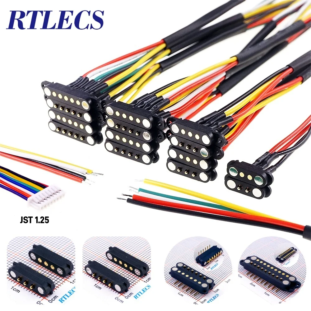
The RTLECS Magnetic Pogo Pin Connector is a precision-engineered electrical interface designed for reliable, high-cycle connections in compact electronic assemblies. As a certified electrician, the immediate focus is on the integrity of the electrical path and the safety implications of its design. These connectors, available in configurations from 2-pin to 9-pin with 2.5mm or 2.80mm spacing, address critical needs in modern portable and modular electronics.
These magnetic pogo pin connectors feature a spring-loaded contact mechanism, which is fundamental to their operational reliability. Each pin is independently sprung, ensuring consistent contact pressure even with minor misalignments or vibrations. The contact surfaces are typically gold-plated, a crucial detail for preventing oxidation and maintaining low contact resistance over thousands of mating cycles. This plating ensures stable current flow.
Consider a portable medical device that requires daily charging. The constant insertion and removal of a standard barrel jack or micro-USB connector can lead to wear, intermittent connections, and eventual failure. The magnetic pogo pin system eliminates the physical stress of insertion, allowing for a smooth, self-aligning connection. This significantly extends the lifespan of the charging port and reduces maintenance requirements, a tangible benefit for both manufacturers and end-users.
Compared to traditional friction-fit connectors, which rely on mechanical force to maintain contact, the spring-loaded design offers superior tolerance for manufacturing variations and environmental factors. This translates directly into a more robust and dependable power and data link, minimizing the risk of accidental disconnections that could interrupt critical operations or data transfer.
Rated for 2 Amperes (2A) of direct current, these connectors are suitable for a wide range of low-power applications. It is imperative that the current draw of the connected device does not exceed this rating. Overcurrent conditions can lead to excessive heat generation at the contact points, potentially melting the connector housing, damaging the connected circuitry, or even initiating an electrical fire. Proper circuit design must incorporate appropriate fusing or current limiting to protect both the connector and the device.
Imagine a scenario where a device, perhaps a handheld diagnostic tool, is drawing 3A through a 2A-rated connector. The connector would quickly overheat, leading to a rapid degradation of the spring tension and contact integrity. This could result in a high-resistance connection, further exacerbating heat buildup, and ultimately causing a catastrophic failure. Adhering to the specified current rating is not merely a recommendation; it is a fundamental safety requirement.
Unlike higher-amperage industrial connectors that feature robust locking mechanisms and larger contact areas, these 2A pogo pins are designed for convenience and compactness. This trade-off means that while they offer ease of use, their application must be carefully matched to the electrical load. For applications requiring higher current, a different connector solution with a higher amperage rating and potentially larger wire gauge compatibility would be necessary to maintain safety and performance standards.
The physical design of these connectors includes both "No Ear" and "Ear Version" options, referring to the presence or absence of mounting flanges. The "No Ear" versions are ideal for flush-mounted applications or where space is extremely limited, relying on the PCB for mechanical support. The "Ear Version," conversely, provides additional mounting points, typically through-hole pins or screw tabs, offering enhanced mechanical stability for applications subject to vibration or frequent handling.
Consider a drone battery pack that needs to be quickly swapped. The "Ear Version" provides a secure, fixed connection point on the drone's chassis, ensuring the connector remains firmly in place despite the forces of flight and repeated battery changes. The magnetic attraction then guides the battery's mating connector into perfect alignment, simplifying the user experience and reducing the chance of damage from fumbling.
This modularity in design allows engineers to select the most appropriate form factor for their specific product. The choice between "Ear" and "No Ear" directly impacts the mechanical integration and long-term durability of the connection within the device's enclosure. It is a small detail with significant engineering implications.
With pin counts ranging from 2 to 9, these connectors offer flexibility for various signal and power requirements. A 2-pin connector is typically used for simple power delivery (positive and negative), while higher pin counts can accommodate additional data lines, ground connections, or control signals. The precise spacing (pitch) of 2.5mm or 2.80mm is critical for PCB layout and ensures compatibility with standard prototyping Boards and compact designs.
Imagine a smart wearable device that needs to transmit sensor data while charging. A 4-pin connector could allocate two pins for power and two for data (e.g., I2C or UART). The consistent contact provided by the pogo pins ensures that both power and data signals remain stable, preventing data corruption or intermittent charging issues. This is crucial for devices where continuous operation and data logging are paramount.
Compared to ribbon cables or individual wire connections, a multi-pin pogo array offers a cleaner, more integrated solution. It reduces the potential for tangled wires, simplifies assembly, and presents a more aesthetically pleasing and robust external interface. The magnetic alignment further enhances this, guiding multiple pins simultaneously into their correct positions, a feature that is particularly beneficial in high-volume manufacturing environments.
The housing material, typically a high-temperature resistant plastic, provides insulation and structural integrity. The spring-loaded pins themselves are often made from brass or beryllium copper, chosen for their excellent electrical conductivity and spring properties. These materials, combined with the gold plating, contribute to the connector's ability to withstand thousands of mating cycles without significant degradation in performance. This is a critical metric.
When a connector is frequently engaged and disengaged, the mechanical wear on the contacts can lead to increased resistance and eventual failure. The spring-loaded design mitigates this by providing a wiping action during connection, which helps to clean the contact surfaces and maintain a low-resistance path. The robust construction ensures that the connector can endure the physical stresses of repeated use in consumer electronics, industrial sensors, or even ruggedized equipment.
Unlike cheaper, unplated connectors that can quickly corrode in humid environments, the gold-plated contacts offer superior environmental resistance. This extends the operational life of the device, particularly in applications where exposure to moisture or corrosive agents is a concern. The investment in quality materials directly translates into long-term reliability and reduced field failures.
RTLECS positions these connectors as a solution for engineers seeking both precision and adaptability. The variety of pin counts and mounting options allows for tailored integration into diverse product designs. The magnetic retention simplifies user interaction, making devices more intuitive and user-friendly. This is a significant design consideration.
Picture a modular robotics platform where different sensor modules need to be quickly attached and detached. The magnetic pogo pins allow for tool-free module swaps, enhancing the platform's versatility and reducing downtime. The secure, yet easily releasable, connection ensures that modules stay in place during operation but can be effortlessly reconfigured as needed.
This level of design flexibility and user convenience sets these magnetic pogo pin connectors apart from more rigid, permanent connection methods. They represent an upgrade for any product requiring frequent, reliable, and user-friendly electrical interfaces. The consistent contact pressure and self-aligning nature minimize the common frustrations associated with traditional connectors, ensuring a seamless experience for both the designer and the end-user. Imagine the satisfaction of a device that always connects perfectly, every single time, without fuss or alignment issues. This is the promise of well-engineered magnetic pogo pins.
Engineering for Connection Reliability
These magnetic pogo pin connectors feature a spring-loaded contact mechanism, which is fundamental to their operational reliability. Each pin is independently sprung, ensuring consistent contact pressure even with minor misalignments or vibrations. The contact surfaces are typically gold-plated, a crucial detail for preventing oxidation and maintaining low contact resistance over thousands of mating cycles. This plating ensures stable current flow.
Consider a portable medical device that requires daily charging. The constant insertion and removal of a standard barrel jack or micro-USB connector can lead to wear, intermittent connections, and eventual failure. The magnetic pogo pin system eliminates the physical stress of insertion, allowing for a smooth, self-aligning connection. This significantly extends the lifespan of the charging port and reduces maintenance requirements, a tangible benefit for both manufacturers and end-users.
Compared to traditional friction-fit connectors, which rely on mechanical force to maintain contact, the spring-loaded design offers superior tolerance for manufacturing variations and environmental factors. This translates directly into a more robust and dependable power and data link, minimizing the risk of accidental disconnections that could interrupt critical operations or data transfer.
Current Handling and Safety Protocols
Rated for 2 Amperes (2A) of direct current, these connectors are suitable for a wide range of low-power applications. It is imperative that the current draw of the connected device does not exceed this rating. Overcurrent conditions can lead to excessive heat generation at the contact points, potentially melting the connector housing, damaging the connected circuitry, or even initiating an electrical fire. Proper circuit design must incorporate appropriate fusing or current limiting to protect both the connector and the device.
Imagine a scenario where a device, perhaps a handheld diagnostic tool, is drawing 3A through a 2A-rated connector. The connector would quickly overheat, leading to a rapid degradation of the spring tension and contact integrity. This could result in a high-resistance connection, further exacerbating heat buildup, and ultimately causing a catastrophic failure. Adhering to the specified current rating is not merely a recommendation; it is a fundamental safety requirement.
Unlike higher-amperage industrial connectors that feature robust locking mechanisms and larger contact areas, these 2A pogo pins are designed for convenience and compactness. This trade-off means that while they offer ease of use, their application must be carefully matched to the electrical load. For applications requiring higher current, a different connector solution with a higher amperage rating and potentially larger wire gauge compatibility would be necessary to maintain safety and performance standards.
Mechanical Design and Application Versatility
The physical design of these connectors includes both "No Ear" and "Ear Version" options, referring to the presence or absence of mounting flanges. The "No Ear" versions are ideal for flush-mounted applications or where space is extremely limited, relying on the PCB for mechanical support. The "Ear Version," conversely, provides additional mounting points, typically through-hole pins or screw tabs, offering enhanced mechanical stability for applications subject to vibration or frequent handling.
Consider a drone battery pack that needs to be quickly swapped. The "Ear Version" provides a secure, fixed connection point on the drone's chassis, ensuring the connector remains firmly in place despite the forces of flight and repeated battery changes. The magnetic attraction then guides the battery's mating connector into perfect alignment, simplifying the user experience and reducing the chance of damage from fumbling.
This modularity in design allows engineers to select the most appropriate form factor for their specific product. The choice between "Ear" and "No Ear" directly impacts the mechanical integration and long-term durability of the connection within the device's enclosure. It is a small detail with significant engineering implications.
Pin Configuration and Signal Integrity
With pin counts ranging from 2 to 9, these connectors offer flexibility for various signal and power requirements. A 2-pin connector is typically used for simple power delivery (positive and negative), while higher pin counts can accommodate additional data lines, ground connections, or control signals. The precise spacing (pitch) of 2.5mm or 2.80mm is critical for PCB layout and ensures compatibility with standard prototyping Boards and compact designs.
Imagine a smart wearable device that needs to transmit sensor data while charging. A 4-pin connector could allocate two pins for power and two for data (e.g., I2C or UART). The consistent contact provided by the pogo pins ensures that both power and data signals remain stable, preventing data corruption or intermittent charging issues. This is crucial for devices where continuous operation and data logging are paramount.
Compared to ribbon cables or individual wire connections, a multi-pin pogo array offers a cleaner, more integrated solution. It reduces the potential for tangled wires, simplifies assembly, and presents a more aesthetically pleasing and robust external interface. The magnetic alignment further enhances this, guiding multiple pins simultaneously into their correct positions, a feature that is particularly beneficial in high-volume manufacturing environments.
Material Science and Durability
The housing material, typically a high-temperature resistant plastic, provides insulation and structural integrity. The spring-loaded pins themselves are often made from brass or beryllium copper, chosen for their excellent electrical conductivity and spring properties. These materials, combined with the gold plating, contribute to the connector's ability to withstand thousands of mating cycles without significant degradation in performance. This is a critical metric.
When a connector is frequently engaged and disengaged, the mechanical wear on the contacts can lead to increased resistance and eventual failure. The spring-loaded design mitigates this by providing a wiping action during connection, which helps to clean the contact surfaces and maintain a low-resistance path. The robust construction ensures that the connector can endure the physical stresses of repeated use in consumer electronics, industrial sensors, or even ruggedized equipment.
Unlike cheaper, unplated connectors that can quickly corrode in humid environments, the gold-plated contacts offer superior environmental resistance. This extends the operational life of the device, particularly in applications where exposure to moisture or corrosive agents is a concern. The investment in quality materials directly translates into long-term reliability and reduced field failures.
The RTLECS Advantage: Precision and Adaptability
RTLECS positions these connectors as a solution for engineers seeking both precision and adaptability. The variety of pin counts and mounting options allows for tailored integration into diverse product designs. The magnetic retention simplifies user interaction, making devices more intuitive and user-friendly. This is a significant design consideration.
Picture a modular robotics platform where different sensor modules need to be quickly attached and detached. The magnetic pogo pins allow for tool-free module swaps, enhancing the platform's versatility and reducing downtime. The secure, yet easily releasable, connection ensures that modules stay in place during operation but can be effortlessly reconfigured as needed.
This level of design flexibility and user convenience sets these magnetic pogo pin connectors apart from more rigid, permanent connection methods. They represent an upgrade for any product requiring frequent, reliable, and user-friendly electrical interfaces. The consistent contact pressure and self-aligning nature minimize the common frustrations associated with traditional connectors, ensuring a seamless experience for both the designer and the end-user. Imagine the satisfaction of a device that always connects perfectly, every single time, without fuss or alignment issues. This is the promise of well-engineered magnetic pogo pins.