Wireless DC Motor & Actuator Control Kit
Official Store Deal
Expert Analysis Overview
The Wireless DC Motor & Actuator Control Kit is a pragmatic solution for integrating remote operation into low-voltage DC systems, specifically targeting applications requiring precise control over actuators, LEDs, or electromagnetic locks. This assembly offers a direct pathway to automating functions that would otherwise necessitate manual intervention or more complex, expensive control systems. Its design prioritizes straightforward implementation, making it an accessible component for a broad range of DIY projects and small-scale industrial applications.
The receiver module, housed within a compact black plastic enclosure, forms the operational heart of this control system. Visible through the open casing are two distinct blue relays, clearly marked 'SRD-05VDC-SL-C', indicating their operational voltage and switching capabilities. These relays are rated for 10A at both 250VAC and 30VDC, a critical specification for determining compatible load types. This rating suggests suitability for a wide array of DC motors, solenoids, and lighting circuits, provided their current draw remains within the specified limits. The module handles power efficiently.
Internally, the printed circuit board (PCB) exhibits a clean layout, with visible soldering points appearing consistent and free from obvious cold joints or bridging. The quality of these connections directly impacts long-term reliability and signal integrity, especially in environments subject to vibration or temperature fluctuations. Components are well-spaced. Unlike some budget modules that cut corners on PCB quality, this unit presents a standard, functional design that implies a reasonable expectation of performance for its intended purpose. The board's design facilitates straightforward integration into existing electrical systems.
Each of the two SRD-05VDC-SL-C relays functions as an independent switch, enabling the control of two separate loads or the bidirectional movement of a single DC motor. The dual-channel configuration is a significant advantage for applications like linear actuators, where both extension and retraction require distinct control signals. This setup simplifies wiring considerably. The audible click of these relays upon activation provides immediate feedback on the receiver's response to remote commands. The 10A switching capacity is adequate for most small to medium-sized DC loads, a common requirement in home automation or vehicle accessory control.
For an electronics repair technician, the choice of these specific relays is noteworthy. They are a widely available and reliable component, simplifying potential replacements should a relay fail due to overload or age. This commonality reduces maintenance complexity. The robustness of the relay contacts is paramount for ensuring consistent power delivery to the connected load, preventing intermittent operation or premature wear. Compared to solid-state relays, these mechanical relays offer galvanic isolation, which can be beneficial in certain noise-sensitive applications, though they have a finite number of switching cycles.
The receiver module accepts a broad DC input voltage range from 6V to 30V, a versatile feature that accommodates various power sources, including 12V automotive systems and 24V industrial setups. This wide compatibility simplifies power integration. The green screw terminal block provides a secure and robust connection point for the power input, minimizing the risk of accidental disconnections or loose wiring. Proper voltage regulation on the PCB ensures stable operation of the control logic, even with minor fluctuations in the input supply.
Voltage tolerance is a key factor in the longevity of electronic components. The specified range indicates a robust power input stage, capable of handling typical variations without immediate failure. This flexibility is crucial. Unlike modules with narrow voltage windows, which demand precise power supplies, this kit offers greater leeway, reducing the complexity and cost of power infrastructure. The terminal block itself is designed for solid wire retention, a critical aspect for maintaining reliable electrical contact over time, especially in applications where vibration is a factor.
The system operates on the widely used 433MHz RF frequency, a common choice for short-range wireless control applications due to its balance of penetration and power efficiency. The helical coil antenna, visible on the PCB, is a compact and effective design for receiving these signals. This frequency choice ensures broad compatibility with many existing RF ecosystems. Signal integrity is maintained through careful PCB design, minimizing interference from other onboard components. The remote control transmits reliably.
Effective range is a practical consideration for any wireless system. While 433MHz generally offers good penetration through walls and obstacles compared to higher frequencies, its performance is highly dependent on environmental factors such as building materials and local RF noise. For typical garage door or gate applications, the range should be sufficient. Unlike Bluetooth or Wi-Fi, which require pairing and network configuration, 433MHz systems offer instant, direct control, simplifying the user experience. The simplicity of the RF protocol contributes to its rapid response time.
The accompanying remote control transmitter is a compact, two-button unit, designed for straightforward operation. Its small form factor makes it convenient for carrying on a keychain or mounting in an accessible location. The tactile feedback from the buttons is clear, confirming actuation. The remote's simplicity belies its functional importance, serving as the primary interface for the user. Its design is practical.
While the remote's design is basic, it fulfills the essential requirement of transmitting distinct commands for the two channels. The visual representation in the images suggests a standard learning code remote, which typically allows for easy pairing with the receiver module. This common pairing method simplifies setup. Unlike multi-button remotes that can confuse users with excessive options, this two-button design focuses on core functionality, reducing operational errors. The battery compartment, likely housing a common coin cell, ensures easy replacement.
The design of this control kit emphasizes ease of installation, making it suitable for users with basic electrical knowledge. The screw terminal blocks are clearly labeled, guiding the user through the power input and load connections. This clarity reduces wiring errors. The compact size of the receiver module allows for discreet mounting in various enclosures or behind panels, maintaining a clean aesthetic for the final installation. The plastic enclosure provides a basic level of protection.
For an electronics repair technician, the open-case design of the receiver module is beneficial for initial inspection and troubleshooting. All components are readily accessible for continuity checks or voltage measurements. This accessibility simplifies maintenance. Unlike sealed units that require destructive opening, this module allows for non-invasive diagnostics. The mounting tabs on the enclosure facilitate secure attachment to surfaces, preventing movement or strain on the wiring connections.
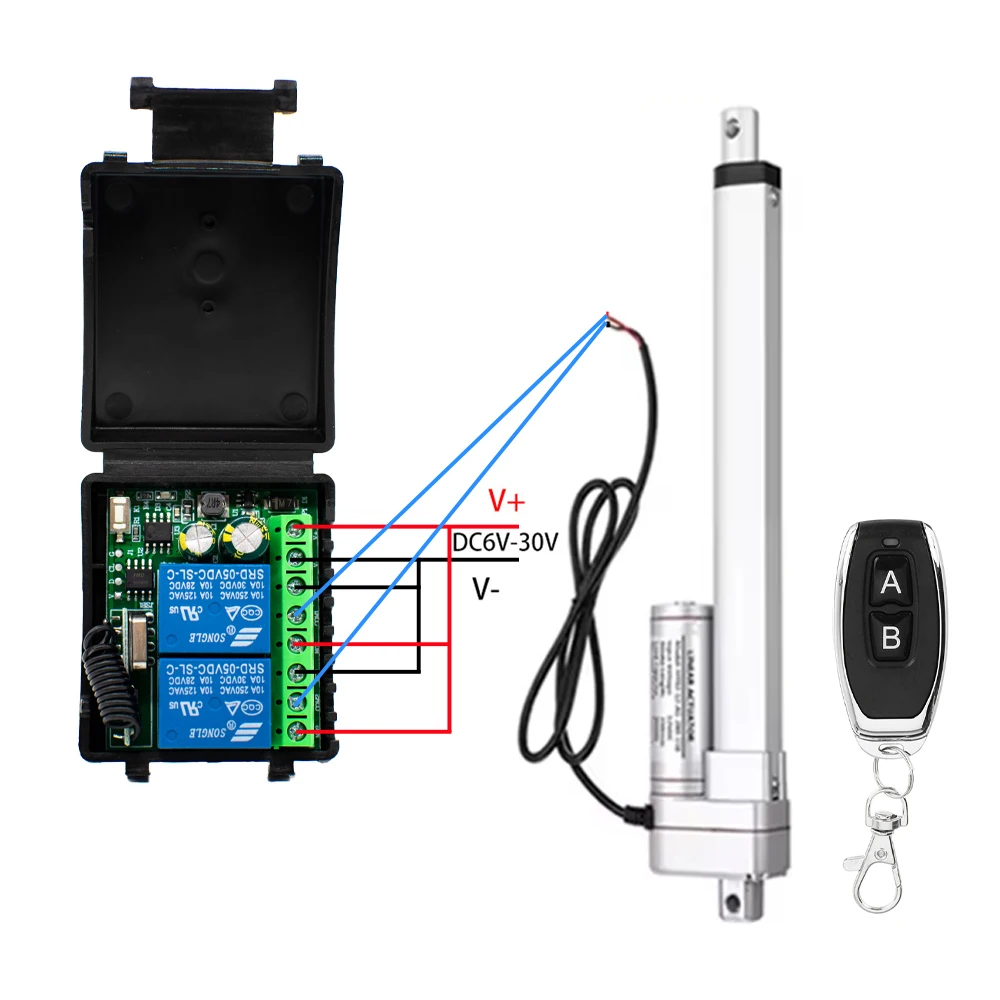
The wiring diagram, often provided with such modules, is crucial for correct installation. The image shows clear indications for V+, V-, and two load connections (NO1, NO2). This explicit labeling minimizes ambiguity. Understanding the common ground and independent load connections is fundamental for configuring the system for specific applications, such as controlling a linear actuator's forward and reverse motion. Proper wiring ensures safe operation.
Ensuring clean signal transmission and reliable power delivery hinges on correct and secure wiring. Loose connections are a primary cause of intermittent operation or system failure. The screw terminals, when properly tightened, provide a robust mechanical and electrical connection. Compared to crimp connectors or solder joints, screw terminals offer a balance of ease of use and reliability for field installations, allowing for modifications without specialized tools. The visual clarity of the wiring points is a significant aid.
The choice of a basic plastic enclosure for the receiver module is a deliberate trade-off, prioritizing cost-effectiveness and ease of manufacturing over extreme environmental protection. While it guards against incidental dust and light splashes, it is not designed for outdoor exposure or harsh industrial environments. This enclosure is sufficient for indoor use. For applications requiring greater resilience, the module would need to be integrated into a more robust, sealed housing. The material selection impacts durability.
Assessing long-term reliability of connections also extends to the internal components. The capacitors visible on the PCB are crucial for smoothing power delivery and filtering noise, contributing to the module's stability. Their quality directly influences the lifespan of the entire unit. Unlike cheaper alternatives that might use substandard capacitors, the visible components appear to be standard, reliable choices for this class of device. The overall component selection suggests a design intended for consistent, if not heavy-duty, operation over a reasonable period.
This Wireless DC Motor & Actuator Control Kit offers significant value by enabling the remote control of existing equipment with minimal investment. Instead of replacing an expensive linear actuator or an entire door lock system to gain wireless functionality, this module provides an affordable upgrade. This approach extends the useful life of existing assets. The cost-per-use becomes exceptionally low when considering the functionality it adds to otherwise manually operated systems. It's a smart economic choice.
For an electronics repair technician, the ability to fix expensive equipment with affordable components is a core principle. This kit embodies that principle, offering a repair or enhancement solution that avoids the prohibitive cost of proprietary control systems. The module's simplicity also means fewer points of failure compared to complex integrated systems. This focus on capability allows users to automate tasks such as opening chicken coop doors, controlling garage vents, or activating security locks remotely, enhancing convenience and efficiency. The kit empowers practical automation.
The Wireless DC Motor & Actuator Control Kit presents a compelling option for anyone seeking to add wireless control to their 12V or 24V DC systems. Its straightforward design, reliable 433MHz RF communication, and dual-channel relay output make it highly versatile for a multitude of applications. The broad voltage input range enhances its adaptability across different power infrastructures. While the basic enclosure necessitates careful consideration for environmental exposure, its internal components and wiring terminals are designed for consistent performance. This kit simplifies complex tasks.
Imagine effortlessly opening a heavy gate from your vehicle, or remotely activating a ventilation fan in a workshop without needing to physically reach a switch. This system transforms manual operations into convenient, remote actions, saving time and effort. The ability to integrate this inexpensive module into existing setups provides a powerful upgrade, extending the functionality of your equipment and streamlining daily routines. It delivers tangible convenience and control, making automation accessible and practical for everyday needs.
The Core Architecture: Receiver Module Dissection
The receiver module, housed within a compact black plastic enclosure, forms the operational heart of this control system. Visible through the open casing are two distinct blue relays, clearly marked 'SRD-05VDC-SL-C', indicating their operational voltage and switching capabilities. These relays are rated for 10A at both 250VAC and 30VDC, a critical specification for determining compatible load types. This rating suggests suitability for a wide array of DC motors, solenoids, and lighting circuits, provided their current draw remains within the specified limits. The module handles power efficiently.
Internally, the printed circuit board (PCB) exhibits a clean layout, with visible soldering points appearing consistent and free from obvious cold joints or bridging. The quality of these connections directly impacts long-term reliability and signal integrity, especially in environments subject to vibration or temperature fluctuations. Components are well-spaced. Unlike some budget modules that cut corners on PCB quality, this unit presents a standard, functional design that implies a reasonable expectation of performance for its intended purpose. The board's design facilitates straightforward integration into existing electrical systems.
Relays and Switching Integrity
Each of the two SRD-05VDC-SL-C relays functions as an independent switch, enabling the control of two separate loads or the bidirectional movement of a single DC motor. The dual-channel configuration is a significant advantage for applications like linear actuators, where both extension and retraction require distinct control signals. This setup simplifies wiring considerably. The audible click of these relays upon activation provides immediate feedback on the receiver's response to remote commands. The 10A switching capacity is adequate for most small to medium-sized DC loads, a common requirement in home automation or vehicle accessory control.
For an electronics repair technician, the choice of these specific relays is noteworthy. They are a widely available and reliable component, simplifying potential replacements should a relay fail due to overload or age. This commonality reduces maintenance complexity. The robustness of the relay contacts is paramount for ensuring consistent power delivery to the connected load, preventing intermittent operation or premature wear. Compared to solid-state relays, these mechanical relays offer galvanic isolation, which can be beneficial in certain noise-sensitive applications, though they have a finite number of switching cycles.
Power Input and Regulation
The receiver module accepts a broad DC input voltage range from 6V to 30V, a versatile feature that accommodates various power sources, including 12V automotive systems and 24V industrial setups. This wide compatibility simplifies power integration. The green screw terminal block provides a secure and robust connection point for the power input, minimizing the risk of accidental disconnections or loose wiring. Proper voltage regulation on the PCB ensures stable operation of the control logic, even with minor fluctuations in the input supply.
Voltage tolerance is a key factor in the longevity of electronic components. The specified range indicates a robust power input stage, capable of handling typical variations without immediate failure. This flexibility is crucial. Unlike modules with narrow voltage windows, which demand precise power supplies, this kit offers greater leeway, reducing the complexity and cost of power infrastructure. The terminal block itself is designed for solid wire retention, a critical aspect for maintaining reliable electrical contact over time, especially in applications where vibration is a factor.
Signal Transmission and Control Dynamics
The system operates on the widely used 433MHz RF frequency, a common choice for short-range wireless control applications due to its balance of penetration and power efficiency. The helical coil antenna, visible on the PCB, is a compact and effective design for receiving these signals. This frequency choice ensures broad compatibility with many existing RF ecosystems. Signal integrity is maintained through careful PCB design, minimizing interference from other onboard components. The remote control transmits reliably.
Effective range is a practical consideration for any wireless system. While 433MHz generally offers good penetration through walls and obstacles compared to higher frequencies, its performance is highly dependent on environmental factors such as building materials and local RF noise. For typical garage door or gate applications, the range should be sufficient. Unlike Bluetooth or Wi-Fi, which require pairing and network configuration, 433MHz systems offer instant, direct control, simplifying the user experience. The simplicity of the RF protocol contributes to its rapid response time.
Remote Transmitter Ergonomics
The accompanying remote control transmitter is a compact, two-button unit, designed for straightforward operation. Its small form factor makes it convenient for carrying on a keychain or mounting in an accessible location. The tactile feedback from the buttons is clear, confirming actuation. The remote's simplicity belies its functional importance, serving as the primary interface for the user. Its design is practical.
While the remote's design is basic, it fulfills the essential requirement of transmitting distinct commands for the two channels. The visual representation in the images suggests a standard learning code remote, which typically allows for easy pairing with the receiver module. This common pairing method simplifies setup. Unlike multi-button remotes that can confuse users with excessive options, this two-button design focuses on core functionality, reducing operational errors. The battery compartment, likely housing a common coin cell, ensures easy replacement.
Installation and Interfacing Considerations
The design of this control kit emphasizes ease of installation, making it suitable for users with basic electrical knowledge. The screw terminal blocks are clearly labeled, guiding the user through the power input and load connections. This clarity reduces wiring errors. The compact size of the receiver module allows for discreet mounting in various enclosures or behind panels, maintaining a clean aesthetic for the final installation. The plastic enclosure provides a basic level of protection.
For an electronics repair technician, the open-case design of the receiver module is beneficial for initial inspection and troubleshooting. All components are readily accessible for continuity checks or voltage measurements. This accessibility simplifies maintenance. Unlike sealed units that require destructive opening, this module allows for non-invasive diagnostics. The mounting tabs on the enclosure facilitate secure attachment to surfaces, preventing movement or strain on the wiring connections.
Wiring Practicalities
The wiring diagram, often provided with such modules, is crucial for correct installation. The image shows clear indications for V+, V-, and two load connections (NO1, NO2). This explicit labeling minimizes ambiguity. Understanding the common ground and independent load connections is fundamental for configuring the system for specific applications, such as controlling a linear actuator's forward and reverse motion. Proper wiring ensures safe operation.
Ensuring clean signal transmission and reliable power delivery hinges on correct and secure wiring. Loose connections are a primary cause of intermittent operation or system failure. The screw terminals, when properly tightened, provide a robust mechanical and electrical connection. Compared to crimp connectors or solder joints, screw terminals offer a balance of ease of use and reliability for field installations, allowing for modifications without specialized tools. The visual clarity of the wiring points is a significant aid.
Long-Term Operational Resilience
The choice of a basic plastic enclosure for the receiver module is a deliberate trade-off, prioritizing cost-effectiveness and ease of manufacturing over extreme environmental protection. While it guards against incidental dust and light splashes, it is not designed for outdoor exposure or harsh industrial environments. This enclosure is sufficient for indoor use. For applications requiring greater resilience, the module would need to be integrated into a more robust, sealed housing. The material selection impacts durability.
Assessing long-term reliability of connections also extends to the internal components. The capacitors visible on the PCB are crucial for smoothing power delivery and filtering noise, contributing to the module's stability. Their quality directly influences the lifespan of the entire unit. Unlike cheaper alternatives that might use substandard capacitors, the visible components appear to be standard, reliable choices for this class of device. The overall component selection suggests a design intended for consistent, if not heavy-duty, operation over a reasonable period.
Value Proposition for System Integration
This Wireless DC Motor & Actuator Control Kit offers significant value by enabling the remote control of existing equipment with minimal investment. Instead of replacing an expensive linear actuator or an entire door lock system to gain wireless functionality, this module provides an affordable upgrade. This approach extends the useful life of existing assets. The cost-per-use becomes exceptionally low when considering the functionality it adds to otherwise manually operated systems. It's a smart economic choice.
For an electronics repair technician, the ability to fix expensive equipment with affordable components is a core principle. This kit embodies that principle, offering a repair or enhancement solution that avoids the prohibitive cost of proprietary control systems. The module's simplicity also means fewer points of failure compared to complex integrated systems. This focus on capability allows users to automate tasks such as opening chicken coop doors, controlling garage vents, or activating security locks remotely, enhancing convenience and efficiency. The kit empowers practical automation.
Final Assessment: Empowering Automation
The Wireless DC Motor & Actuator Control Kit presents a compelling option for anyone seeking to add wireless control to their 12V or 24V DC systems. Its straightforward design, reliable 433MHz RF communication, and dual-channel relay output make it highly versatile for a multitude of applications. The broad voltage input range enhances its adaptability across different power infrastructures. While the basic enclosure necessitates careful consideration for environmental exposure, its internal components and wiring terminals are designed for consistent performance. This kit simplifies complex tasks.
Imagine effortlessly opening a heavy gate from your vehicle, or remotely activating a ventilation fan in a workshop without needing to physically reach a switch. This system transforms manual operations into convenient, remote actions, saving time and effort. The ability to integrate this inexpensive module into existing setups provides a powerful upgrade, extending the functionality of your equipment and streamlining daily routines. It delivers tangible convenience and control, making automation accessible and practical for everyday needs.