WOKLS DIN Rail Spring-Loaded Power Distribution Block
Official Store Deal
Expert Analysis Overview
The WOKLS DIN Rail Spring-Loaded Power Distribution Block is a critical component for efficient and secure electrical distribution within industrial and commercial control panels. This device streamlines complex wiring configurations, offering a robust alternative to traditional screw-type terminals and busbar systems. Its design prioritizes both installation speed and long-term connection reliability, addressing common pain points in electrical panel assembly and maintenance.
This design implies a significant reduction in wiring complexity. Instead of daisy-chaining multiple devices or using individual terminal blocks for each connection, a single distribution block centralizes the power feed. This simplifies circuit layout. It also minimizes the number of individual connections, which inherently reduces potential failure points within an electrical system.
Compared to traditional methods like using multiple individual screw terminals or custom busbar assemblies, these blocks offer a pre-engineered, standardized solution. Screw terminals often require meticulous tightening and periodic re-tightening to prevent loosening due to vibration or thermal cycling. Busbar systems, while robust, typically demand custom fabrication or specialized components, adding to both cost and installation time. The WOKLS block provides a ready-to-install, off-the-shelf alternative that accelerates panel construction.
This method ensures a consistent and reliable contact pressure on the conductor. Unlike screw terminals, which can loosen over time due to vibration, thermal expansion and contraction, or improper initial torque, spring clamps maintain a constant force. This inherent vibration resistance is crucial in industrial environments where machinery operation can induce significant mechanical stress on electrical connections. A secure connection prevents arcing. Arcing can lead to overheating, insulation breakdown, and ultimately, electrical fires.
Traditional screw terminals, while widely used, require careful attention to torque specifications. Under-torquing leads to loose connections and potential overheating, while over-torquing can damage the conductor or the terminal itself. The spring-loaded system removes this variable, providing a consistent and optimal clamping force every time. This consistency enhances safety and reduces the likelihood of intermittent faults, which are notoriously difficult to diagnose in complex control systems.
This standardized mounting system offers unparalleled modularity and space efficiency. Components can be arranged densely and logically within a panel, maximizing available space. The ability to easily snap components on and off the rail simplifies initial installation and subsequent modifications or expansions. This is a significant advantage in dynamic industrial settings where control systems frequently evolve.
In contrast, components that require individual screw mounting to a backplate consume more time and often lead to less organized panel layouts. The DIN rail system, supported by these terminal blocks, promotes a clean, professional aesthetic and functional layout. This improves troubleshooting efficiency. It also reduces the risk of wiring errors by providing a clear, structured path for conductors.
This range of options allows for precise tailoring to specific circuit requirements. A smaller 1-in-6-out block might be ideal for distributing power to a localized group of sensors or actuators. The larger 1-in-24-out block is suitable for more extensive distribution needs, such as powering multiple relays, contactors, or control devices from a single source. This versatility reduces the need for multiple different types of distribution components.
Without these varied configurations, an electrician might be forced to use multiple smaller blocks or resort to less efficient wiring methods to achieve the desired number of outputs. The availability of different output counts within the same product family ensures consistency in installation methods and component aesthetics across a control panel. This simplifies inventory management. It also streamlines design processes for electrical engineers.
Plastic housing provides excellent electrical insulation, preventing accidental contact with live parts and minimizing the risk of short circuits between adjacent terminals. The choice of flame-retardant material is critical in electrical applications. It ensures that in the event of an internal fault or overheating, the component will not contribute to the spread of fire. The robust nature of engineering plastics also provides mechanical protection against impacts and environmental factors within a control cabinet.
Inferior materials could lead to premature failure, compromised insulation, or even fire hazards. The visible quality of the plastic and the consistent design across the product range suggest adherence to reasonable manufacturing standards. Proper material selection is paramount. It directly impacts the safety and longevity of the entire electrical system.
It is imperative that these distribution blocks are always used in conjunction with appropriate overcurrent protection devices, such as circuit breakers or fuses, upstream of the input. The block itself is a distribution point, not a protective device. Without proper overcurrent protection, a fault on any of the output circuits could lead to excessive current flow through the block, causing overheating and potential damage or fire.
Electrical codes mandate that all conductors and components be protected against overcurrent. An electrician must calculate the maximum anticipated load for each output circuit and the total load for the input, then select circuit breakers or fuses accordingly. This ensures the safety of the wiring, the connected devices, and the distribution block itself. Never exceed the rated current. This is a fundamental safety principle.
This method drastically reduces installation time compared to screw terminals, especially when wiring a large number of connections. It also minimizes installer fatigue. The consistent connection quality, independent of installer skill in torquing screws, leads to more reliable and uniform installations. This is a major benefit for large-scale projects or repetitive assembly tasks.
Traditional wiring often involves twisting strands, inserting them under a screw, and then tightening. This process is slower and more prone to errors, such as stray strands causing short circuits or insufficient contact pressure. The push-in system offers a cleaner, faster, and more consistent connection, which translates directly into labor cost savings and improved system reliability.
In a complex control panel, the ability to quickly disconnect and reconnect circuits without tools or significant effort can dramatically reduce downtime during fault finding. If a component needs to be replaced or a circuit rerouted, the process is straightforward. This modularity and ease of access contribute to a more maintainable electrical system.
Systems relying on permanent or difficult-to-modify connections can lead to extended downtime and increased labor costs during maintenance. The WOKLS distribution blocks, with their simple wire release mechanism, empower technicians to perform tasks efficiently. This improves operational continuity. It also reduces the overall cost of ownership for the electrical installation.
Imagine a control panel where every wire is neatly organized, securely terminated, and easily identifiable. Picture the confidence in knowing that each connection is consistently reliable, minimizing the risk of intermittent faults or safety hazards. Envision the speed at which new circuits can be added or existing ones modified, reducing downtime and maximizing productivity. This distribution block delivers that level of precision and efficiency, transforming chaotic wiring into a meticulously managed electrical system, ensuring long-term operational stability and safety for any industrial or commercial application.
Streamlined Power Distribution Architecture
Core Functionality and Design Philosophy
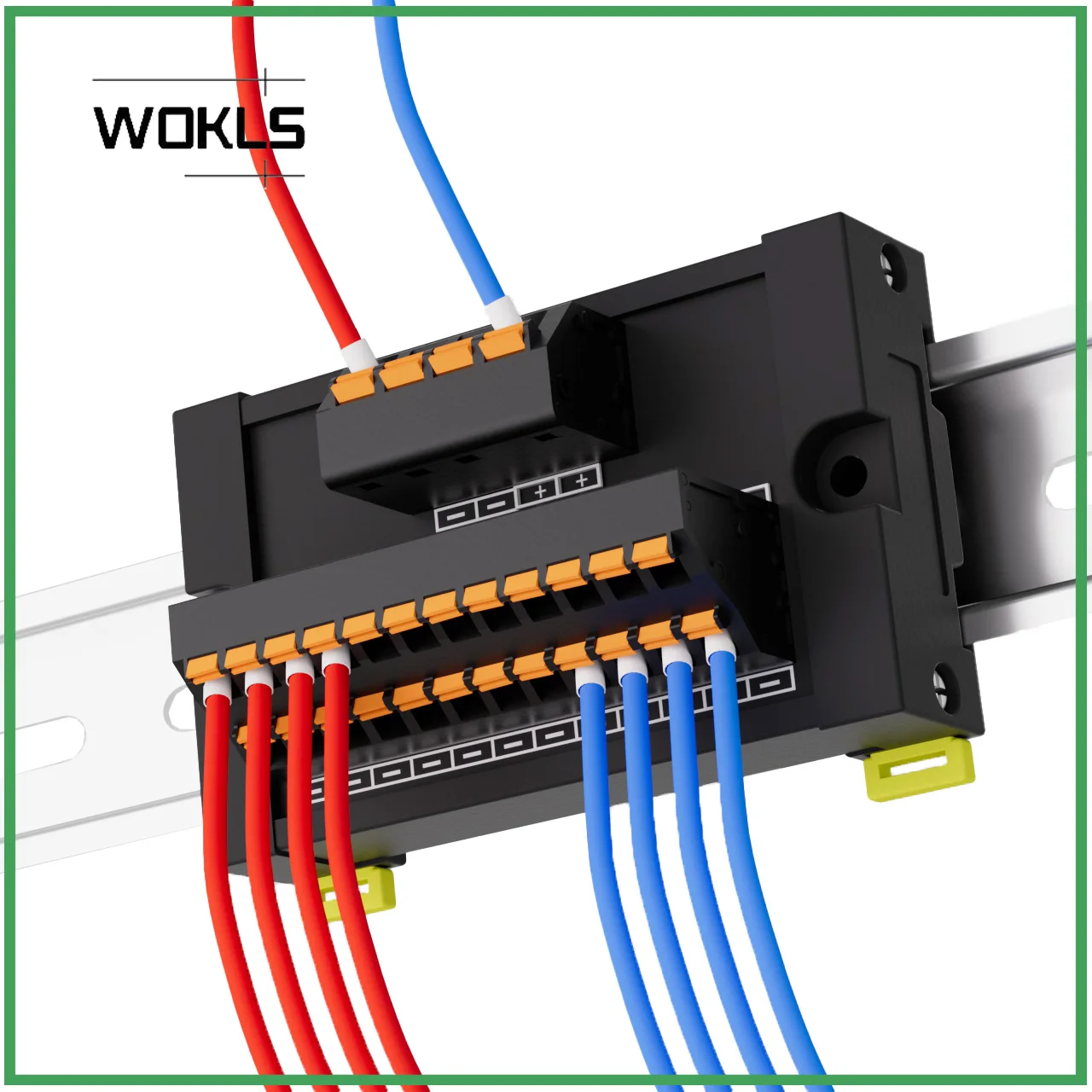
The visual evidence presents a series of black-bodied terminal blocks, clearly designed for DIN rail mounting. These units feature multiple output terminals, distinguished by their orange spring-loaded push-in mechanisms. The primary input is typically a single larger terminal, distributing power to several smaller outputs. This configuration is evident across the various models shown, from the compact 1-in-6-out to the larger 1-in-24-out variants.This design implies a significant reduction in wiring complexity. Instead of daisy-chaining multiple devices or using individual terminal blocks for each connection, a single distribution block centralizes the power feed. This simplifies circuit layout. It also minimizes the number of individual connections, which inherently reduces potential failure points within an electrical system.
Compared to traditional methods like using multiple individual screw terminals or custom busbar assemblies, these blocks offer a pre-engineered, standardized solution. Screw terminals often require meticulous tightening and periodic re-tightening to prevent loosening due to vibration or thermal cycling. Busbar systems, while robust, typically demand custom fabrication or specialized components, adding to both cost and installation time. The WOKLS block provides a ready-to-install, off-the-shelf alternative that accelerates panel construction.
Wiring Integrity and Connection Reliability
The most prominent feature is the spring-loaded push-in terminal technology. This mechanism involves a spring clamp that secures the conductor once it is inserted, eliminating the need for screws. Wires are simply stripped and pushed into the terminal, often with a small tool for leverage on larger gauges or for releasing the wire.This method ensures a consistent and reliable contact pressure on the conductor. Unlike screw terminals, which can loosen over time due to vibration, thermal expansion and contraction, or improper initial torque, spring clamps maintain a constant force. This inherent vibration resistance is crucial in industrial environments where machinery operation can induce significant mechanical stress on electrical connections. A secure connection prevents arcing. Arcing can lead to overheating, insulation breakdown, and ultimately, electrical fires.
Traditional screw terminals, while widely used, require careful attention to torque specifications. Under-torquing leads to loose connections and potential overheating, while over-torquing can damage the conductor or the terminal itself. The spring-loaded system removes this variable, providing a consistent and optimal clamping force every time. This consistency enhances safety and reduces the likelihood of intermittent faults, which are notoriously difficult to diagnose in complex control systems.
Effortless Panel Integration and Scalability
Standardized Mounting for Professional Setups
All depicted models are explicitly designed for DIN rail mounting. The DIN rail, a standardized metal rail, provides a universal mounting platform for various electrical components within control cabinets. The blocks feature integrated clips or mounting points that snap onto the rail, allowing for quick and tool-free installation or removal.This standardized mounting system offers unparalleled modularity and space efficiency. Components can be arranged densely and logically within a panel, maximizing available space. The ability to easily snap components on and off the rail simplifies initial installation and subsequent modifications or expansions. This is a significant advantage in dynamic industrial settings where control systems frequently evolve.
In contrast, components that require individual screw mounting to a backplate consume more time and often lead to less organized panel layouts. The DIN rail system, supported by these terminal blocks, promotes a clean, professional aesthetic and functional layout. This improves troubleshooting efficiency. It also reduces the risk of wiring errors by providing a clear, structured path for conductors.
Versatile Configuration Options
The product line includes several configurations: 1-in-6-out, 1-in-12-out, and 1-in-24-out. The images clearly show these variations, with the 1-in-6-out being a single-row design and the 1-in-12-out and 1-in-24-out models featuring two rows of output terminals. The dimensions provided for each variant confirm their distinct sizes and capacities.This range of options allows for precise tailoring to specific circuit requirements. A smaller 1-in-6-out block might be ideal for distributing power to a localized group of sensors or actuators. The larger 1-in-24-out block is suitable for more extensive distribution needs, such as powering multiple relays, contactors, or control devices from a single source. This versatility reduces the need for multiple different types of distribution components.
Without these varied configurations, an electrician might be forced to use multiple smaller blocks or resort to less efficient wiring methods to achieve the desired number of outputs. The availability of different output counts within the same product family ensures consistency in installation methods and component aesthetics across a control panel. This simplifies inventory management. It also streamlines design processes for electrical engineers.
Ensuring Electrical Integrity and Operational Safety
Material Selection and Durability Considerations
The housing of these terminal blocks appears to be constructed from a robust, flame-retardant plastic, typically polyamide (PA) or similar engineering polymer. The internal contacts, though not directly visible, are invariably made from a conductive metal, likely copper alloy, to ensure low resistance and high current carrying capacity. The spring mechanism itself would be made from a high-grade spring steel.Plastic housing provides excellent electrical insulation, preventing accidental contact with live parts and minimizing the risk of short circuits between adjacent terminals. The choice of flame-retardant material is critical in electrical applications. It ensures that in the event of an internal fault or overheating, the component will not contribute to the spread of fire. The robust nature of engineering plastics also provides mechanical protection against impacts and environmental factors within a control cabinet.
Inferior materials could lead to premature failure, compromised insulation, or even fire hazards. The visible quality of the plastic and the consistent design across the product range suggest adherence to reasonable manufacturing standards. Proper material selection is paramount. It directly impacts the safety and longevity of the entire electrical system.
Current Handling and Overcurrent Protection
While specific current ratings are not explicitly visible in the provided images, the physical size of the terminals and the typical applications for such distribution blocks imply a certain current carrying capacity. The input terminal appears larger than the output terminals, indicating it is designed to handle the sum of the currents drawn by all connected loads. Proper wire gauge selection is critical.It is imperative that these distribution blocks are always used in conjunction with appropriate overcurrent protection devices, such as circuit breakers or fuses, upstream of the input. The block itself is a distribution point, not a protective device. Without proper overcurrent protection, a fault on any of the output circuits could lead to excessive current flow through the block, causing overheating and potential damage or fire.
Electrical codes mandate that all conductors and components be protected against overcurrent. An electrician must calculate the maximum anticipated load for each output circuit and the total load for the input, then select circuit breakers or fuses accordingly. This ensures the safety of the wiring, the connected devices, and the distribution block itself. Never exceed the rated current. This is a fundamental safety principle.
Practical Application and Maintenance Advantages
Simplified Wiring Procedures
The push-in connection method significantly simplifies the wiring process. After stripping the wire to the correct length, it is simply pushed into the terminal. For smaller gauges, this can often be done by hand. For larger gauges or for releasing wires, a small screwdriver or specialized tool is used to depress the spring mechanism, allowing for insertion or removal.This method drastically reduces installation time compared to screw terminals, especially when wiring a large number of connections. It also minimizes installer fatigue. The consistent connection quality, independent of installer skill in torquing screws, leads to more reliable and uniform installations. This is a major benefit for large-scale projects or repetitive assembly tasks.
Traditional wiring often involves twisting strands, inserting them under a screw, and then tightening. This process is slower and more prone to errors, such as stray strands causing short circuits or insufficient contact pressure. The push-in system offers a cleaner, faster, and more consistent connection, which translates directly into labor cost savings and improved system reliability.
Troubleshooting and System Modifications
The spring-loaded mechanism also facilitates quick and easy wire removal. By depressing the spring, the wire can be extracted without damaging the conductor or the terminal. This ease of modification is invaluable during troubleshooting, system upgrades, or reconfigurations.In a complex control panel, the ability to quickly disconnect and reconnect circuits without tools or significant effort can dramatically reduce downtime during fault finding. If a component needs to be replaced or a circuit rerouted, the process is straightforward. This modularity and ease of access contribute to a more maintainable electrical system.
Systems relying on permanent or difficult-to-modify connections can lead to extended downtime and increased labor costs during maintenance. The WOKLS distribution blocks, with their simple wire release mechanism, empower technicians to perform tasks efficiently. This improves operational continuity. It also reduces the overall cost of ownership for the electrical installation.
Imagine a control panel where every wire is neatly organized, securely terminated, and easily identifiable. Picture the confidence in knowing that each connection is consistently reliable, minimizing the risk of intermittent faults or safety hazards. Envision the speed at which new circuits can be added or existing ones modified, reducing downtime and maximizing productivity. This distribution block delivers that level of precision and efficiency, transforming chaotic wiring into a meticulously managed electrical system, ensuring long-term operational stability and safety for any industrial or commercial application.